| CPC G09G 3/3685 (2013.01) [G09G 3/2096 (2013.01); G09G 3/3614 (2013.01); G09G 2310/08 (2013.01); G09G 2320/0209 (2013.01); G09G 2320/0247 (2013.01)] | 11 Claims |
|
1. A display apparatus, comprising:
a display panel, comprising a plurality of data lines comprising a first data line group and a second data line group, and a plurality of gate lines disposed intersecting the plurality of data lines;
a gate driver, supplying a gate selection signal to each of the plurality of gate lines; and
a plurality of data drivers, provided for each predetermined number of data lines, each generating a positive polarity gradation data signal higher than a predetermined standard voltage and a negative polarity gradation data signal lower than the standard voltage in response to a video signal, and alternately and repeatedly executing an operation of supplying the positive polarity gradation data signal to the first data line group and supplying the negative polarity gradation data signal to the second data line group and an operation of supplying the positive polarity gradation data signal to the second data line group and supplying the negative polarity gradation data signal to the first data line group, wherein
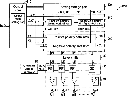
each of the plurality of data drivers comprises:
a control part, executing either a first output mode or a second output mode, and switching from the first output mode to the second output mode or from the second output mode to the first output mode within a predetermined period at intervals of the predetermined period, wherein,
in the first output mode, a signal in which a data pulse having a positive polarity voltage value corresponding to a luminance level of each pixel appears in a predetermined cycle is output as the positive polarity gradation data signal based on the video signal, and a signal in which a data pulse having a negative polarity voltage value corresponding to a luminance level of each pixel appears in the predetermined cycle with a phase different from that of the positive polarity gradation data signal is output as the negative polarity gradation data signal based on the video signal, and
in the second output mode, the signal in which a data pulse having the positive polarity voltage value corresponding to the luminance level of each pixel appears in the predetermined cycle is output as the positive polarity gradation data signal based on the video signal, and the signal in which a data pulse having the negative polarity voltage value corresponding to a luminance level of each pixel appears in the predetermined cycle with the same phase as that of the positive polarity gradation data signal is output as the negative polarity gradation data signal based on the video signal, wherein
the negative polarity gradation data signal in the first output mode is shifted in a direction of being delayed with respect to the phase of the positive polarity gradation data signal, and the control part reduces a time length of the phase shift of the negative polarity gradation data signal with respect to the positive polarity gradation data signal as a wiring length of the plurality of gate lines wired from the plurality of data lines that receive the gradation data signals to an output terminal of the gate driver is reduced.
|