| CPC G03B 21/204 (2013.01) [G02B 26/008 (2013.01); G03B 21/16 (2013.01)] | 20 Claims |

|
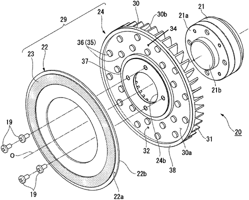
1. A wavelength conversion device comprising:
a rotary drive section;
a wheel substrate having thermal conductivity and rotated around a central axis by the rotary drive section;
a phosphor layer formed around the central axis on a first surface of the wheel substrate; and
a cooling fin unit disposed on a second surface opposite to the first surface of the wheel substrate, wherein
the cooling fin unit has a base part to be bonded to the wheel substrate, and a plurality of radiator fins disposed at an opposite side to the wheel substrate side of the base part,
the second surface of the wheel substrate includes a first area corresponding to the phosphor layer, and a second area located closer to the central axis than the first area,
the second surface of the wheel substrate and a surface at the wheel substrate side of the base part are separated from each other to form a space between the wheel substrate and the base part,
a coupling part configured to thermally couple the second surface of the wheel substrate and the surface at the wheel substrate side of the base part is disposed in at least the second area of the second surface, and
the coupling part is disposed closer to the central axis than the phosphor layer.
|