| CPC G01R 19/32 (2013.01) [H02M 3/3376 (2013.01)] | 12 Claims |

|
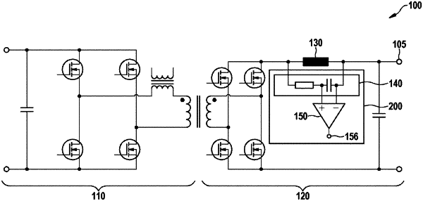
1. A device (200) for measuring a current through a choke (130) of a voltage converter (100), the device comprising:
an integrator circuit (140), an amplifier circuit, and an NTC resistor (160),
wherein a load current of the voltage converter (100) flows through the choke (130) and the choke (130) is connected on the output side to an output terminal (105) of the voltage converter (100),
wherein the integrator circuit (140) is arranged in parallel with the choke (130) and comprises a series circuit having an integrator resistor (142) and an integrator capacitor (144),
wherein the integrator capacitor (144) is also connected to the output terminal (105) of the voltage converter (100) and a center tap is formed between the integrator resistor (142) and the integrator capacitor (144) as the output of the integrator circuit (140) and an integrator output signal is present at the output of the integrator circuit (140),
wherein the amplifier circuit comprises an inverting and a non-inverting amplifier input terminal (152, 154) and an amplifier output terminal (156), and the non-inverting amplifier input terminal (154) is supplied with an amplifier input signal depending on the integrator output signal, and a voltage signal characterizing the current through the choke (130) is present at the amplifier output terminal (156) of the amplifier circuit,
wherein
the NTC resistor (160) is arranged in the feedback path of the amplifier circuit between the inverting amplifier input terminal (152) and the amplifier output terminal (156).
|