| CPC G01R 19/2513 (2013.01) [H02J 3/381 (2013.01); H02J 2203/20 (2020.01); H02J 2300/28 (2020.01)] | 5 Claims |

|
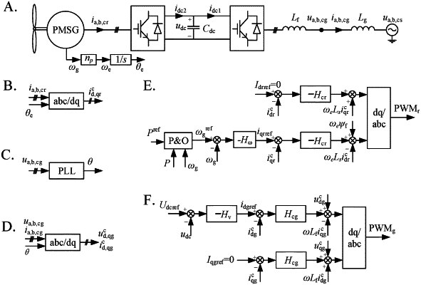
1. A method for analyzing stability of a PMSG-WT connected to a weak power grid considering influence of power control, wherein the PMSG-WT comprises a wind turbine, a generator, an MSC, a DC capacitor, a GSC, a filter, an MSC controller, and a GSC controller; the MSC controller comprises a power loop, a rotating speed loop, and a machine-side current loop; the GSC controller comprises a voltage loop and a grid-side current loop; and the method comprises the following steps:
step 1: acquiring main parameters of the PMSG-WT, establishing mathematical models of the wind turbine, the generator and the MSC, the MSC controller, the DC capacitor, the GSC and the filter, and the GSC controller, respectively, performing linearization in a dq coordinate system, and calculating steady-state operation parameters to obtain small-signal models of the wind turbine, the generator and the MSC, the MSC controller, the DC capacitor, the GSC and the filter, and the GSC controller;
step 2: modeling the power loop in the MSC controller based on a describing function method, wherein its mathematical expression is:
 where ε represents a perturbation step length of the power loop, Tp represents a control period of the power loop, Pref represents a reference value of the output power of the PMSG-WT, P represents an output power of the PMSG-WT, Pn represents an output power of the PMSG-WT at a current sampling moment n, Pn−1 represents an output power of the PMSG-WT at a previous sampling moment, ωg represents a rotating speed of the generator, ωgref represents a reference value of the rotating speed of the generator, ωg,n represents a rotating speed of the generator at the current sampling moment, and ωg,n−1 represents a rotating speed of the generator at the previous sampling moment; sgn(x) is a sign function, when x≥0, sgn(x)=1, and when x<0, sgn(x)=−1; considering an actual power-rotating speed curve of the PMSG-WT, then:
 where ωmpp represents a rotating speed of the generator at a maximum power point; and then, the power loop model can be simplified as:
 wherein the sign function in the formula can be modeled by using a describing function, and the describing function thereof is:
 in the formula, A represents an amplitude of an input signal;
step 3: considering the influence of the weak AC power grid, combining the linear parts of the small-signal models of the weak power grid and the power loop with the small-signal models established in step 1, and deriving a transfer function G(s) of the linear part of a system; and
step 4: drawing G(s) and −1/N(A) curves in a complex plane, and analyzing the stability of the system based on the describing function method, wherein the method is specifically that if G(s) contains a pole of the right half plane, the system must be unstable; if the G(s) does not contain the pole of the right half plane, then judging the stability of the system through the relationship between a G(s) curve and a −1/N(A) curve:
a. if the G(s) curve does not surround the −1/N(A) curve, the system is stable and does not oscillate;
b. if the G(s) curve and the −1/N(A) curve intersect, the system is critically stable, at this time, the system oscillates at a constant amplitude and a constant frequency, and the frequency and the amplitude of the oscillation can be calculated by the following formula:
 where G(jω)=GRe(ω)+jGIm(ω), GRe means to find the real part of a complex number, GIm means to find the imaginary part of the complex number, ω0 represents an angular frequency of the oscillation, and A0 represents the amplitude of the oscillation; and
c. if the G(s) curve surrounds the −1/N(A) curve, the system is unstable.
|