| CPC G01N 31/12 (2013.01) | 7 Claims |

|
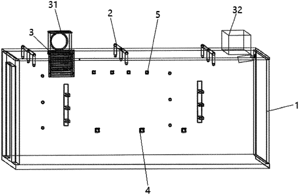
1. A combined platform for testing fireproof materials for cables, characterized in that the combined platform comprises:
a main frame (1) for providing operating space;
an air circulation system (3) comprising a fresh air supply unit (31) for supplying fresh air into the operating space and an exhaust gas treatment unit (32) for treating the gas in the operating space under set conditions;
an open flame system (4) for providing an open flame for testing the cables in the operating space;
a water circulation system (2) for supplying water at least to the exhaust gas treatment unit (32) and the operating space for the exhaust gas treatment and spraying of the open flame, respectively; and
a control system (5) for collecting at least indicator parameters in the operating space, the results of which are used as a basis for the operation of the water circulation system (2), the air circulation system (3) and the open flame system (4);
wherein the exhaust gas treatment unit (32) comprises a plasma dust removal unit (33) and a spray unit (34) connected to the control system (5), respectively,
wherein the plasma dust removal unit (33) is arranged inside a spray space of the spray unit (34), and comprises a gas inlet (331) in communication with the interior of the operating space and gas outlets (332) in communication with a bottom of the spray unit (34),
wherein the spray unit (34) comprises a spray port (341) arranged at top thereof, an gas supply port (342) and an exhaust port (343), the spray port (341) being in communication with the water circulation system (2), the gas supply port (342) being in communication with the gas inlet (331) for the gas to enter the plasma dust removal unit (33), and the exhaust port (343) being used for discharging the gas after spraying;
wherein the plasma dust removal unit (33) comprises two half-shells (333) hinged symmetrically left and right, a ventilation plate (334), an anode wire (335) and a cathode cylinder (336);
wherein the two half-shells (333) form a three-layer space arranged from top to bottom, the three-layer space includes a top-level space, a middle-level space and a bottom level space, the gas inlet (331) is disposed in the top-level space, the ventilation plate (334) is installed in the middle-level space to divide the top-level space and the bottom-level space and allows air circulation from the top-level space to the bottom-level space, the anode wire (335) is installed between the ventilation plate (334) and a bottom of the two half-shells (333) and is jacketed inside the cathode cylinder (336), the cathode cylinder (336) is fixed in the bottom-level space, and the gas outlets (332) are in communication with interior of the cathode cylinder (336); and
wherein the ventilation plate (334) is a cylindrical plate structure and is symmetrically provided with a number of gas passages (3341) around a central axis, wherein the gas flow direction of the gas passages (3341) is arranged obliquely with respect to the central axis.
|