| CPC G01N 21/05 (2013.01) [B01L 3/502715 (2013.01); B01L 2200/025 (2013.01); B01L 2300/0609 (2013.01); B01L 2300/0654 (2013.01); B01L 2300/0663 (2013.01); G01N 2201/02 (2013.01)] | 24 Claims |

|
1. An assembly for testing a sample fluid to determine a sample property, the assembly comprising,
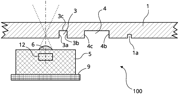
a cartridge comprising, an elongated channel along which a sample fluid can flow wherein the elongated channel is defined by a groove in the cartridge, one or more elements which are configured to manipulate light in a predefined manner, and wherein said one or more elements are located in a predefined position relative to the elongated channel so that the one or more elements can facilitate alignment of an optical device with the elongated channel;
an optical device which is configured such that the optical device can be selectively operated to emit light;
a means for moving the optical device with respect to the cartridge, which can move the optical device from a first position in which optical device is not aligned with the elongated channel, over the one or more elements, to a second position in which the optical device is aligned with the elongated channel so that light emitted by the optical device can be incident on sample fluid flowing in the channel to test the sample fluid;
a sensor which is configured to output a signal which is representative of the light which the sensor received, wherein said sensor receives light which has been reflected by the cartridge when the optical device is in said first position, and wherein the sensor receives light which has been manipulated by the one or more elements as the optical device is moved over the one or more elements, and wherein said received manipulated light causes a predefined change in the output of the sensor so that the output of the sensor can be used to determine the position of the optical device relative to the elongated channel.
|