| CPC G01N 1/08 (2013.01) [G01N 33/24 (2013.01)] | 9 Claims |

|
1. A method for monitoring a forestry microenvironment, comprising the following steps:
S1: moving a forestry detection vehicle to a monitoring position, starting a sampling device installed on the forestry detection vehicle, and drilling a sampling end into soil by the sampling device;
S2: inserting the sampling device on the forestry detection vehicle into the soil at a corresponding depth;
S3: disconnecting the sampled soil, and withdrawing the sampling device from the forestry detection vehicle to complete the sampling process;
S4: weighing the above soil sample quantitatively, preparing the soil sample into a standard solution for soil detection, and detecting the standard solution for soil detection;
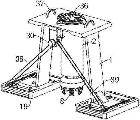
the sampling device in S1 comprises a rack (1); the rack (1) is arranged as a portal frame; an outer sleeve (2) is arranged in the rack (1); an upper end of the outer sleeve (2) is rotatably installed on the rack (1); an inner end in the outer sleeve (2) is provided with an inner disc (3); the inner disc (3) is rotatably installed at an inner side of the outer sleeve (2);
the inner disc (3) is fixedly provided with a connecting frame (4); an end of the connecting frame (4) is fixedly connected to the rack (1); a sampling mechanism is arranged in the outer sleeve (2); and a lower end of the sampling mechanism extends outside the outer sleeve (2) and is connected with the inner disc (3);
the sampling mechanism further comprises an inner cylinder (5); an upper end of the inner cylinder (5) extends into the outer sleeve (2); the inner cylinder (5) is provided with a plurality of upper and lower equidistant perforations (6); the perforations (6) penetrate through the inner cylinder (5) and the plurality of perforations (6) located at the same height are distributed in a circular array; storage grooves (7) are arranged at bottoms in the perforations (6); a bottom of the inner cylinder (5) is fixedly provided with a drill bit (8); the inner side of the outer sleeve (2) is provided with a plurality of spline grooves (9) distributed in a circular array; an outer side of the inner cylinder (5) is fixedly provided with a plurality of splines (10) distributed in a circular array; the splines (10) are matched with splines of the spline grooves (9); the upper end in the inner cylinder (5) is rotatably provided with a connecting piece (11); the sampling mechanism further comprises a screw rod (12); the screw rod (12) is arranged in the inner cylinder (5); an upper end of the screw rod (12) is rotatably installed a bottom of the inner disc (3); a lower end of the screw rod (12) penetrates through the connecting piece (11) and is in threaded connection with the connecting piece (11); the top of the inner disc (3) is rotatably provided with a connecting shaft (14); the connecting shaft (14) penetrates through the inner disc (3) and is fixedly connected with the screw rod (12); a top of the outer sleeve (2) is fixedly provided with a connecting ring (15); the connecting ring (15) is sleeved and fixedly provided with a tooth ring (16);
sealing plugs (17) are arranged in the storage grooves (7); the sealing plugs (17) are in interference fit with the storage grooves (7); the sampling mechanism further comprises a plurality of connecting ropes (18); the connecting ropes (18) penetrate through the inner cylinder (5) and the storage grooves (7) and are fixedly connected with a plurality of the sealing plugs (17) one of a plurality of columns ; the-upper ends of the connecting ropes (18) are fixedly connected to the bottom of the inner disc (3); the sampling mechanism further comprises a driving assembly; and the driving assembly is installed on the rack (1) and connected with the connecting shaft (14).
|