| CPC G01M 3/3263 (2013.01) [G01L 13/00 (2013.01)] | 3 Claims |

|
1. A pneumatic leak meter based on absolute pressure drop measurements that compensates for ambient variations and temperature of a part of a test object being measured, as well as mechanical deformations of the part of the test object caused by pressure being applied, and that comprises two pressure drop measurement circuits and associated electronics so that leaks can be measured by subtracting pressure values of the two measuring circuits and associated electronics, comprising:
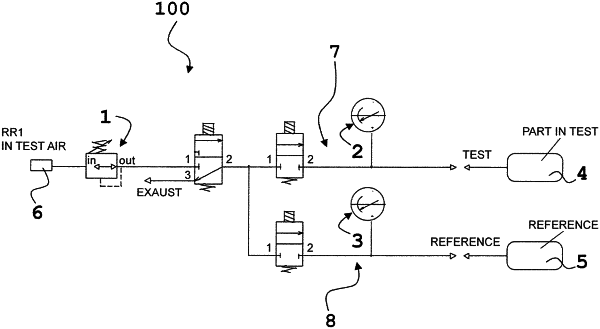
a common pneumatic valve for pressurizing an object being tested, namely, on a pneumatic pressurization section (1) of said test object,
a first circuit with a dedicated pneumatic valve (7) for selectively coupling the first circuit to said pneumatic pressurization section (1) during a pressurization phase and for selectively decoupling the first circuit from the pneumatic pressurization section (1) during a measurement phase,
a first pressure meter (2) for first circuit for monitoring the pressurization of the test object; said pressure meter being a relative pressure meter operating relative to ambient temperature;
a first pneumatic line dedicated to the first circuit that connects the pressure meter with the pneumatic pressurization section of the test object,
such that the first circuit (7) acts as a first absolute pressure drop measurement circuit for the purpose of measuring decay over time of the test object;
a second circuit with a dedicated pneumatic valve (8) with a second pressure meter (3) operating relative to ambient temperature connected to a second pneumatic line dedicated to the second circuit; such that the second circuit (8) acts as a second absolute pressure drop measurement circuit for the purpose of measuring decay over time of the test object;
Wherein, in the case of a symmetrical differential measurement the second pneumatic line is connected to a reference object being tested in terms of temperature and expansion, said referenced object being a leak-free object; and in the case of an asymmetrical differential measurement, the second pneumatic line is not connected to the reference object;
Wherein in the case an asymmetrical differential measurement, associated electronics (FIG. 2) are configured to acquire both pressure values measured by the first pressure meter and the second pressure meter, and therefore to continuously sample differences between both pressure values; and
Wherein, in the case of a symmetrical differential measurement, the associated electronics (FIG. 2) are configured to acquire and save in a permanent data array, a measurement trend of the reference object, and determine, during measurement, a difference in real time between an acquired wave and the saved array, point by point in phase with time, as such ensuring that the resulting differential measurement is free from and unaffected by mechanical stress phenomena and variations in ambient temperature.
|