| CPC G01J 9/0246 (2013.01) [G02B 5/3083 (2013.01); G01J 2009/0226 (2013.01); G01J 2009/0253 (2013.01); G01J 2009/0284 (2013.01)] | 6 Claims |

|
1. An interferometer for measuring a frequency shift in an input wave, the interferometer comprising:
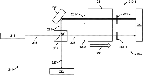
(a) a splitter, the splitter reflecting a first portion of the input wave along a first path located within a first interferometer arm, the splitter transmitting a second portion of the input wave along a second path located within a second interferometer arm, wherein each of the first and second portions of the input wave are reflected back to the splitter to yield a recombined wave, the recombined wave producing an interference pattern; and
(b) a common dispersive element located within both the first path in the first interferometer arm and the second path in the second interferometer arm;
(c) wherein a shift in frequency of a wave transmitted through the dispersive element modifies the path within its corresponding interferometer arm, wherein a change in the path with an interferometer arm caused by a frequency shift in the input wave creates a corresponding phase change in the interference pattern, the corresponding phase change in the interference pattern being utilized to calculate the frequency shift in the input wave.
|