| CPC G01F 23/14 (2013.01) [G01F 22/00 (2013.01); G01F 23/18 (2013.01)] | 19 Claims |

|
1. A fluid level measurement system, comprising:
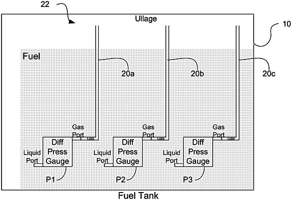
a first pressure sensor disposed inside a fluid tank at a first elevation relative to a fixed tank vertical axis;
a second pressure sensor disposed inside the fluid tank at a second elevation relative to the fixed tank vertical axis, the second elevation different from the first elevation,
wherein the first pressure sensor and the second pressure sensor are configured to provide a signal indicative of a sensed pressure, and fluid height in the fixed tank vertical axis is calculated from
i) a scale factor obtained by dividing a known vertical spacing between the first and second pressure sensors in the fixed tank vertical axis by a difference in the pressure sensed between the second pressure sensor and the first pressure sensor, wherein the pressure sensed by the first and second pressure sensors is obtained while both the first and the second pressure sensors are immersed in the fluid, and
ii) a sensed pressure from one of the first or second pressure sensors.
|