| CPC F28F 1/12 (2013.01) [F25B 39/02 (2013.01)] | 18 Claims |

|
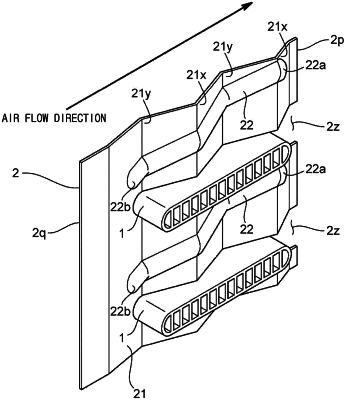
1. A heat exchanger comprising:
a heat transfer tube formed in a flat shape; and
a plurality of fins,
wherein a refrigerant flowing inside the heat transfer tube exchanges heat with air flowing between the plurality of fins,
wherein each fin of the plurality of fins comprises:
a heat transfer expansion surface comprising a plurality of peak portions and a plurality of valley portions provided along an air flow direction, and
a drain structure provided to overlap each of the plurality of peak portions and the plurality of valley portions of the heat transfer expansion surface, and
wherein the drain structure includes a convex portion formed on the heat transfer expansion surface,
wherein the heat transfer tube includes a plurality of heat transfer tubes arranged in multiple stages in a vertical direction,
wherein each heat transfer tube has a flat surface facing in an upward direction and a flat surface facing in a downward direction,
wherein each fin is formed in a long shape extending in the vertical direction,
wherein the plurality of heat transfer tubes passes through at least one of the plurality of fins,
wherein a cutting groove is formed at a position corresponding to the plurality of heat transfer tubes in a first long side of each fin,
wherein a second long side of each fin extends in a straight line from an upper end to a lower end, and
wherein the drain structure is provided to drain water droplets toward the second long side of the fin.
|