| CPC F25B 25/005 (2013.01) [F25B 39/00 (2013.01); H05K 7/20936 (2013.01); B64D 2013/0614 (2013.01); B64D 2013/0618 (2013.01); F25B 2400/23 (2013.01)] | 20 Claims |
|
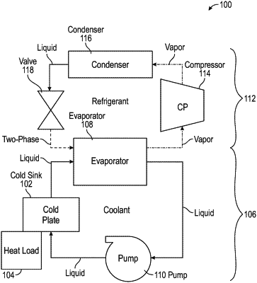
1. A cooling system comprising:
a cold sink thermally coupled to a heat load;
a separator configured to separate liquid and vapor portions of a working fluid; and
a cooling cycle having a vapor loop and a liquid loop, the cooling cycle having the working fluid configured to pass through both the vapor loop and the liquid loop,
wherein the vapor loop comprises the separator, a compressor, a condenser, and a valve, wherein a vapor form of the working fluid flows from the separator into the compressor, and the working fluid then flows to the condenser, and then through the valve, and returned to the separator; and
wherein the liquid loop comprises the cold sink, the separator, and a pump, wherein a liquid form of the working fluid flows from the separator into the pump and the working fluid is increased in pressure and supplied to the cold sink and then returned to the separator,
wherein the separator is arranged downstream from the cold sink as a downstream separator; and
an upstream separator is arranged upstream from the cold sink and configured to separate liquid and vapor portions of the working fluid, wherein a liquid portion of the working fluid is sourced from the upstream separator and directed into the cold sink.
|