| CPC F24H 1/102 (2013.01) [F24H 9/146 (2013.01); F28F 1/00 (2013.01); F28F 9/005 (2013.01); H05B 3/40 (2013.01); F24H 2250/02 (2013.01); H05B 2203/013 (2013.01); H05B 2203/021 (2013.01); H05B 2203/033 (2013.01)] | 25 Claims |
|
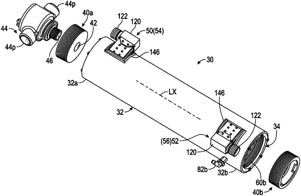
1. An inline heater comprising:
a heater core, said heater core comprising:
a heat spreader assembly comprising:
a tubular heat spreader that extends axially along a longitudinal axis and that comprises an external surface, said heat spreader assembly comprising a fluid inlet and a fluid outlet;
at least one conduit that extends helically about said longitudinal axis of said tubular heat spreader between said fluid inlet and said fluid outlet to define a fluid heating flow path that is engaged with said tubular heat spreader and that fluidically connects said fluid inlet and said fluid outlet;
said heat spreader assembly further comprising an electrically operated heating element for heating the tubular heat spreader, wherein said at least one heat transfer channel comprises opposite first and second side walls and bottom wall, wherein said at least one conduit is in contact with said first and second side walls and said bottom wall; and
a purge manifold that externally covers said tubular heat spreader and closes said at least one heat transfer channel such that purge passages are defined between the channel walls and the purge manifold around the at least one conduit.
|