| CPC F23D 14/70 (2013.01) [F23D 14/58 (2013.01); F23D 14/82 (2013.01); F23R 3/286 (2013.01)] | 11 Claims |

|
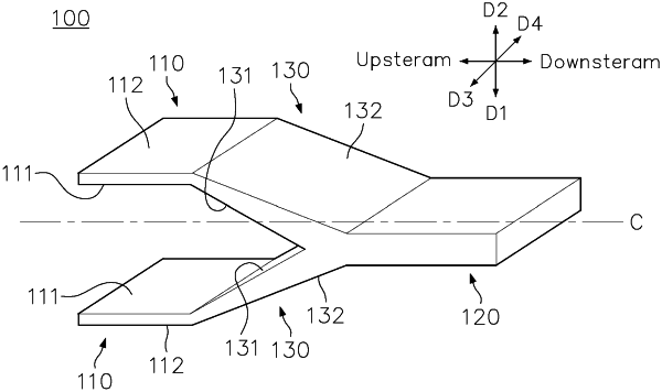
1. An injection nozzle for injecting fuel and compressed air into a combustion chamber of a combustor of a gas turbine, the injection nozzle comprising:
an inlet portion through which the fuel and the compressed air are introduced;
an outlet portion disposed downstream of the inlet portion in a flow direction of fluid and configured to discharge the fuel and compressed air to the combustion chamber;
an intermediate portion connected obliquely to each of the inlet portion and the outlet portion: and
an imaginary center line extending from the outlet portion along the flow direction of fluid and passing through a center of the outlet portion,
wherein the inlet portion comprises a pair of inlet portions, each being shaped as a first rectangular hollow; the outlet is shaped as a second rectangular hollow; and each of the pair of inlet portions and the outlet portion are substantially parallel to each other,
wherein the fuel enters into each of the pair of inlet portions through an upstream end of each of the pair of inlet portions; and the compressed air enters into each of the pair of inlet portions through a plurality of air holes located on walls of each of the pair of inlet portions,
wherein the walls, which have opposing sides, include at least two air holes from the plurality of air holes, with one air hole present on each side of the opposing sides; and
the plurality of air holes is disposed downstream of the upstream end of each of the pair of inlet portions,
wherein one direction perpendicular to the center line is a first direction, a direction opposite to the first direction is a second direction, and directions perpendicular to the center line and perpendicular to the first and second directions are third and fourth directions, respectively,
wherein the pair of inlet portions is symmetrically disposed with respect to the center line interposed therebetween while being spaced apart from the center line in the first direction and the second direction,
wherein the intermediate portion includes a pair of intermediate portions symmetrically disposed with respect to the center line interposed therebetween,
wherein the pair of intermediate portions are inclined from each of the pair of inlet portions toward the center line, converging closer to the center line toward downstream ends of the pair of intermediate portions,
wherein among walls of the pair of intermediate portions disposed inside and outside in the first and second directions, two walls disposed closer to the center line are first intermediate walls and two walls disposed outside in the first and second directions are second intermediate walls, and each of the pair of intermediate portions is formed such that a distance between the first intermediate wall and the second intermediate wall increases toward a downstream side and a width of each of the pair of intermediate portions in the third and fourth directions is constant or slightly decreases toward the downstream side.
|