| CPC F21V 29/57 (2015.01) [F21V 19/007 (2013.01); F21V 29/503 (2015.01); F21V 29/507 (2015.01); F21V 31/005 (2013.01); F21Y 2103/10 (2016.08)] | 9 Claims |

|
1. An infrared lamp tube heat dissipation automatic control system, including:
an elongated housing, whose section is concave to form an accommodating space, the bottom of the elongated housing is provided with at least one installation hole;
at least one lamp holder corresponding to the installation hole arranged at the bottom of the elongated housing;
at least one halogen bulb arranged on the lamp holder, and the upper section of the halogen bulb protrudes into the accommodating space;
a light-transmitting board arranged on the top of the elongated housing;
two left and right covers arranged on the left and right sides of the elongated housing respectively, and a flow hole is provided on the two left and right covers relative to the accommodating space;
wherein the infrared lamp tube further includes an automatic control system for heat dissipation, and the automatic control system for heat dissipation includes:
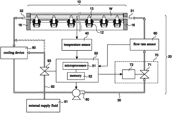
a circulation line, which includes an input end and an output end, respectively connected to the flow holes of the right and left covers, for injecting coolant into the accommodating space of the infrared lamp tube and circulating it, so as to cool down the halogen bulb;
a temperature sensor is arranged in the infrared lamp tube to detect the temperature of the coolant in the accommodating space;
a controller, including a microprocessor and a memory, is electrically connected to the temperature sensor, and calculates the temperature of the coolant;
a flow rate sensor, arranged on the circulation line to detect the flow rate of the coolant and transmit the value to the controller;
a flow control valve, including a first control valve and a driving unit, the driving unit receives an instruction signal from the controller to control the first control valve to adjust its flow;
a pump, installed on the circulation line and electrically connected to the controller, for pumping the coolant to circulate;
a cooling device, installed on the circulation line, to lower the temperature of the coolant flowing out from the output end; and
according to the temperature of the coolant in the accommodating space and the value provided by the flow rate sensor, the controller calculates the optimal flow rate of the coolant in a proportional mode that the higher the temperature, the faster the flow rate, and then control the flow rate by the flow control valve, so as to achieve predetermined coolant temperature and perform contact heat dissipation to the halogen bulb.
|