| CPC F17D 3/12 (2013.01) [B01F 25/316 (2022.01); B05B 7/2445 (2013.01); C02F 1/688 (2013.01); F17D 1/08 (2013.01); Y10T 137/4891 (2015.04)] | 20 Claims |

|
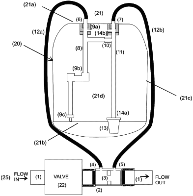
1. A fluid injection system for dispensing a solution into a fluid flow in a flow line, the fluid injection system comprising:
a storage tank having a base material to be dispensed therein;
a connector for connection to a fluid flow line, the connector comprising:
an outlet port for diverting fluid from the flow line into the tank for generating product comprising a mixture of base material and fluid;
an inlet port for returning fluid and/or product back into the fluid flow line; and
a restrictor provided between the inlet and outlet ports, the restrictor sized to control a flow of fluid into the tank via the outlet port;
an inlet dip tube provided inside the tank, the inlet dip tube receiving fluid from the outlet port and dispensing the fluid into the tank;
an outlet dip tube provided inside the tank, the outlet dip tube receiving the base material and/or product; and
a mixing chamber connected between the inlet dip tube and the outlet dip tube, the mixing chamber receiving a portion of the fluid from the inlet dip tube and base material from the outlet dip tube, wherein the mixing chamber is configured to mix the fluid with the base material to create the product,
wherein the product is injected back into the fluid flow line via the inlet port, and
wherein the inlet dip tube is adjustable between:
a first position to dispense the fluid at a bottom of the tank;
a second position to dispense the fluid at a top of the tank; and
a third position, between the first and second positions, to dispense the fluid into the tank.
|