| CPC F17C 13/04 (2013.01) [F17C 13/025 (2013.01); G05D 16/2022 (2019.01); F17C 2203/0617 (2013.01); F17C 2205/0326 (2013.01); F17C 2205/0382 (2013.01); F17C 2205/0394 (2013.01); F17C 2221/012 (2013.01); F17C 2223/0123 (2013.01); F17C 2250/0434 (2013.01); F17C 2250/0636 (2013.01); F17C 2270/0184 (2013.01)] | 8 Claims |

|
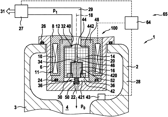
1. A method (200) for operating a tank device (1) for storing compressed fluids, having a tank (2), a valve device (100), a feed line (29), a throughflow regulating element (27) arranged in the feed line (29), and a control unit (64), wherein the valve device (100) comprises a magnet device (11), by means of which magnet device (11) the opening and closing process of the valve device (100) can be controlled, wherein the magnet device (11) comprises a magnet coil (10), wherein a characteristic map (80) is stored in the control unit (64), in which characteristic map (80) reference pressure differences (70) are stored with respectively associated electrical current intensities for the magnet coil (10), wherein the electrical current intensity is selected such that the valve device (100) is still open, wherein an initial electrical current intensity is stored in the characteristic map (80), the method comprising the following steps:
a. applying (60) the initial electrical current intensity to the magnet coil (10);
b. ascertaining (61) a pressure p0 in the tank (2) and ascertaining (61) a pressure p1 in the feed line (29) between the valve device (100) and the throughflow regulating element (27);
c. determining (62) the difference between the pressure p0 in the tank (2) and the pressure p1 in the feed line (29) between the valve device (100) and the throughflow regulating element (27);
d. assigning (63) the determined difference between the pressure p0 in the tank (2) and the pressure p1 in the feed line (29) between the valve device (100) and the throughflow regulating element (27) to one of the reference pressure differences (70) in the characteristic map (80) such that,
when the determined difference between the pressure p0 in the tank (2) and the pressure p1 in the feed line (29) between the valve device (100) and the throughflow regulating element (27) can be assigned to one of the reference pressure differences (70):
i. selecting (64) an electrical current intensity, assigned to the determined reference pressure difference (70), for the magnet coil (10);
ii. applying (65) the selected electrical current intensity to the magnet coil (10);
iii. cyclically repeating (66) steps a. to d.;
when the determined difference between the pressure p0 in the tank (2) and the pressure p1 in the feed line (29) between the valve device (100) and the throughflow regulating element (27) cannot be assigned to one of the reference pressure differences (70): returning (67) to step a.
|