| CPC F16L 37/36 (2013.01) [F16L 37/12 (2013.01); F16L 37/23 (2013.01); F16L 55/07 (2013.01); B67D 7/36 (2013.01); F17C 2205/037 (2013.01)] | 20 Claims |

|
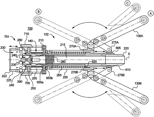
1. A coupler for connecting a tank to a receptacle, the coupler comprising:
a housing;
a probe including an outer surface and configured to translate longitudinally within the housing;
a handle assembly configured to cause the probe to translate within the housing, wherein the handle assembly is movable between a decoupled position at which the tank is capable of being disconnected from the receptacle, a coupled position at which the tank is capable of being connected to the receptacle, and a venting position at which venting of fluid is enabled;
a ball cage;
a plurality of balls disposed in the ball cage; and
a slidable sleeve coupled to the outer surface of the probe and configured to translate longitudinally with the probe, wherein the slidable sleeve is configured to slide in a first longitudinal direction to cause the plurality of balls to translate radially to lock the coupler to the receptacle, and wherein the slidable sleeve includes a collar defining a plurality of channels that are positioned radially and extending axially along the collar and configured to receive bearings of the receptacle in the coupled position and the venting position to prevent rotation of the coupler relative to the receptacle.
|