| CPC F16K 27/029 (2013.01) [F16K 17/04 (2013.01); F16K 31/0655 (2013.01)] | 20 Claims |
|
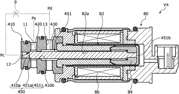
1. A capacity control valve comprising:
a valve housing provided with a suction port through which a suction fluid of suction pressure passes, and a control port through which a control fluid of control pressure passes;
a valve element configured to be driven by a solenoid;
a spring that biases the valve element in a direction opposite to a driving direction by the solenoid; and
a CS valve formed by a CS valve seat and the valve element and configured for opening and closing a communication between the control port and the suction port by a movement of the valve element, wherein
the control pressure is controlled by opening and closing the CS valve,
the valve housing is provided with a guide hole configured to connect a first space in which the CS valve is housed to a second space into which a discharge fluid of a discharge pressure is introduced,
the valve element or a sliding rod which is a separate body facing and being separated from the valve element in an axial direction is slidably fitted into the guide hole,
the valve element or the sliding rod has a pressure receiving portion includes at least one pressure receiving surface which receives the discharge pressure in the axial direction,
all the pressure receiving surfaces face toward a side opposed to the solenoid in the axial direction, receive the discharge pressure in a direction in which the CS valve is closed, and form whole the pressure receiving portion,
a contact portion of the valve element which is brought into contact with the CS valve seat is positioned on a side of the solenoid with respect to the CS valve seat in the axial direction, and
the CS valve seat is disposed between the pressure receiving portion and the solenoid in the axial direction.
|