| CPC F16J 15/3492 (2013.01) [F16J 12/00 (2013.01); F16J 15/3452 (2013.01)] | 8 Claims |

|
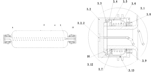
1. An inflation control apparatus for an IV-type hydrogen storage container, wherein the apparatus comprises a rack, a container liner, a rotary inflation connector, an inflation core tube, a temperature and pressure sensor, an air compressor, a valve I, an air heater, an electrically controlled flow regulating valve, and a controller;
seal heads at the two ends of the container liner are rotationally installed on the rack;
the rotary inflation connector comprises a static component and a rotating component, the rotating component is rotatable relative to the static component, and the rotating component is fixedly connected with the seal head of the container liner;
the inflation core tube is located in the container liner, the inflation core tube is provided with air holes thereon, and the two ends thereof are respectively fixedly connected with the static component of the rotary inflation connector;
the temperature and pressure sensor is located in the container liner;
the air compressor supplies air to the air heater via the valve I, and the air heater passes the air heated to a set temperature into an air inlet of the inflation core tube, an air outlet of the inflation core tube is connected to an air inlet of the electrically controlled flow regulating valve, and an air outlet of the electrically controlled flow regulating valve is connected with an air inlet of the air compressor;
the controller is connected with a signal wire of the temperature and pressure sensor, and controls the size of a valve port of the electrically controlled flow regulating valve according to a value detected by the temperature and pressure sensor, thus adjusting an air flow;
the static component comprises an end cap I, an end cap II and a static ring;
the rotating component comprises a movable ring, a movable ring seat, a spring, and a spring gasket;
the end cap I is sleeved on the seal head of the container liner, and is rotatably connected with the seal head, and is not movable axially along the seal head;
the movable ring seat is sleeved on the seal head of the container liner, located in the inner side of the end cap I, is rotatable along with the seal head, and is not movable axially along the seal head;
the spring is sleeved on the seal head of the container liner and located in the movable ring seat;
an inner ring of the spring gasket is fixed on the seal head of the container liner, and an outer ring of the spring gasket is fixed on the movable ring seat, rotates along with the seal head and the movable ring seat, and cooperates with the movable ring seat to compress the spring;
an inner ring of the movable ring is fixed on the seal head of the container liner, an outer ring of the movable ring is fixed on the movable ring seat, and rotates along with the seal head and the movable ring seat, an annular end surface I is in sealing contact with the spring gasket, and a plurality of dynamic pressure grooves are evenly arranged in an annular end surface II, and the rotation direction of the dynamic pressure grooves is consistent with the rotation direction of the container liner;
the static ring is fixed in the end cap II, and is provided with an inflation hole I;
the end cap II is fixedly connected with the end cap I, so that the static ring is in contact with the annular end surface II of the movable ring, the end cap II is provided with an inflation hole II and an inflation hole III thereon, the inflation hole II is aligned with the inflation hole I, and the inflation hole III is fixedly connected with an end of the inflation core tube;
the inflation control apparatus for the IV-type hydrogen storage container further comprises a diverter valve block I, a valve II and a valve III;
an air outlet of the air compressor is connected with an air inlet of the diverter valve block I, and an air outlet I, an air outlet II and an air outlet III of the diverter valve block I are respectively connected with an air inlet of the valve I, an air inlet of the valve II, and an air inlet of the valve III, the air outlet of the valve I is connected with an air inlet of the air heater, and the air outlets of the valve II and valve III are respectively connected with the inflation holes II on the two end caps II, and inflation is conducted between the static ring and the movable ring through the inflation hole II and the inflation hole I; and
the air inlet of the diverter valve block I is in communication with all of the air outlet I, the air outlet II and the air outlet III; and the air outlet I, the air outlet II and the air outlet III are independent of each other.
|