| CPC F16J 15/14 (2013.01) [B21D 53/92 (2013.01); F16J 15/3272 (2013.01); B23P 2700/01 (2013.01); B23P 2700/12 (2013.01); B64C 1/00 (2013.01); Y10T 29/49297 (2015.01); Y10T 29/49826 (2015.01); Y10T 29/49947 (2015.01); Y10T 29/49957 (2015.01); Y10T 29/4997 (2015.01); Y10T 29/49993 (2015.01)] | 12 Claims |

|
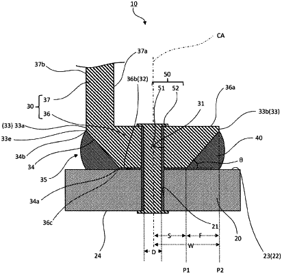
1. A seal structure configured to seal, by using a seal material, between a first opposing surface of a first part and a second opposing surface of a second part, the first part and the second part being joined to each other by a fastener, wherein:
the second part includes
an insertion hole which is open on the second opposing surface and through which the fastener is inserted,
a chamfered surface including a first end connected to an edge of the second opposing surface, the chamfered surface being inclined relative to the second opposing surface, and
an end surface including an edge connected to a second end of the chamfered surface, the end surface being inclined relative to the chamfered surface;
a space sandwiched between the chamfered surface and the first opposing surface forms a chamfered portion accommodating the seal material protruding from between the first opposing surface and the second opposing surface; and
when a diameter of the insertion hole is represented by D, in a direction perpendicular to a central axis of the insertion hole, the first end of the chamfered surface is provided at a position away from the central axis of the insertion hole by one and a half times the diameter D or more, and the second end of the chamfered surface is provided at such a position that a distance between the second end and the central axis of the insertion hole or between the second end and a line passing through central axes of a plurality of insertion holes is three times the diameter D or less.
|