| CPC F16H 7/08 (2013.01) [F16H 2007/081 (2013.01); F16H 2007/0842 (2013.01); F16H 2007/0872 (2013.01); F16H 2007/0893 (2013.01); F16H 2007/0897 (2013.01)] | 6 Claims |

|
1. A chain tensioner comprising:
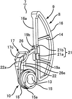
a lever including a sliding contact surface, which is configured to come into sliding contact with a chain, and a boss portion; and
a torsion coil spring including a coil portion fitting into the boss portion, a fixed-side support arm extending from one end of the coil portion, and a lever-side support arm extending from the other end of the coil portion, wherein
the fixed-side support arm is configured to abut against a contact portion which is a fixed member and the lever-side support arm is configured to abut against a contact surface provided on the lever to apply a biasing force of the torsion coil spring to the lever for applying tension to the chain via the sliding contact surface,
the fixed-side support arm includes
a locking portion, and
a pressing portion,
the lever includes a spring housing portion configured to house the locking portion, and an engaging portion integrally formed with the level and configured to lock the locking portion housed in the spring housing portion in a state in which a biasing force is applied,
the fixed-side support arm is configured to move from a first position to a second position, the first position being a position where the locking portion is housed in the spring housing portion and is locked by the engaging portion, the second position being a position where the locking of the locking portion by the engaging portion is released and the locking portion is removed from the spring housing portion, and
the torsion coil spring is configured such that the fixed-side support arm moves in an unwinding direction of the torsion coil spring in response to a release of the locking of the locking portion by the engaging portion.
|