| CPC F16H 1/22 (2013.01) [B25J 9/102 (2013.01); B25J 11/0045 (2013.01); F16H 37/16 (2013.01); F16H 57/021 (2013.01); F16H 57/023 (2013.01); F16H 57/031 (2013.01); H02K 5/00 (2013.01); H02K 7/08 (2013.01); H02K 7/116 (2013.01); F16H 2057/02034 (2013.01); F16H 2057/02073 (2013.01)] | 8 Claims |

|
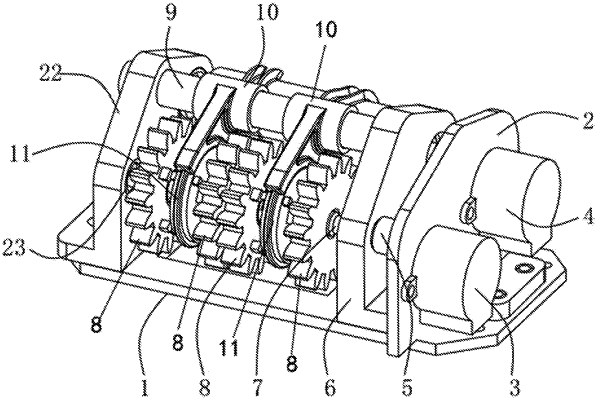
1. An integrated power distribution apparatus for a cooking robot, comprising:
a bottom plate;
a motor fixing base, wherein the motor fixing base is fixedly mounted on one side of a surface of the bottom plate;
a power motor, wherein the power motor is fixedly mounted on one side of the motor fixing base and located above the bottom plate;
a control motor, wherein the control motor is fixedly mounted on a surface of the motor fixing base and located on the one side of the motor fixing base on which the power motor is located;
a shaft coupler, wherein two shaft couplers are provided, and the two shaft couplers are respectively arranged on one side of the power motor and the control motor and located on the surface of the motor fixing base;
a fixed support, wherein the fixed support is fixedly mounted on the surface of the bottom plate and located on one side of the two shaft couplers;
a rotation output shaft, wherein two rotation output shafts are provided, and the two rotation output shafts are respectively arranged on a surface of the fixed support and located on one side of the fixed support opposite to the two shaft couplers;
a power output gear, wherein four power output gears are provided, and the four power output gears are sequentially arranged from left to right on one side of the rotation output shaft;
a placement base, wherein the placement base is fixedly mounted on the surface of the bottom plate and located on one side of the power output gears; and
a bearing, wherein two bearings are provided, and the two bearings are respectively arranged on two sides of an interior of the placement base; and
the one side of the fixed support is fixedly connected with a fixed shaft, a synchronous wheel fork is sleeved on both sides of a surface of the fixed shaft, and power synchronous wheels are arranged inside the two synchronous wheel forks and located on two sides of the power output gears; and
one end of the rotation output shaft associated with the power motor is fixedly connected with a roller selector, both sides of a surface of the roller selector are provided with a groove, the two grooves are internally provided with an offset point, and cylindrical blocks are arranged in the two grooves and located on one side of the roller selector;
when the power motor rotates, the power motor drives the power synchronous wheels to rotate, while the power output gears remain stationary;
when one of the synchronous wheel forks pushes one of the power synchronous wheels to couple with one of the power output gears, the one of the power synchronous wheels drives the corresponding one of the power output gears to rotate and the remaining gears remain stationary.
|