| CPC F16F 1/02 (2013.01) | 4 Claims |

|
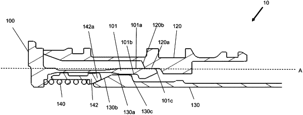
1. A biasing system for an actuator, the system comprising:
a lock sleeve, wherein the lock sleeve includes a first surface and a second surface;
a lock shaft, wherein the lock shaft includes a first surface, a second surface and a third surface;
a tine having a tine finger extending along a longitudinal axis, wherein the tine finger includes a first surface, a second surface, a third surface and a protrusion;
a biasing member, wherein the biasing member includes a first end; and
a biasing spring;
wherein the biasing member and the biasing spring are configured to maintain a position of the tine finger away from the longitudinal axis in the direction of the lock sleeve when the lock sleeve and lock shaft are deployed, in use;
wherein, when the lock sleeve is returned, the tine finger is biased against the lock sleeve to prevent the lock sleeve from returning to a locked position before the lock shaft is able to return to a locked position;
wherein the system includes a locked position, an intermediate position and a transition position;
wherein, in the locked position, the tine finger is in a relaxed state and is sandwiched between the first surface of the lock shaft and the first surface of the lock sleeve, and wherein the tine finger is parallel to the longitudinal axis; and
wherein the first end of the biasing member is in contact with the second surface of the lock shaft such that the biasing spring is held in a compressed state by the second surface of the lock shaft;
wherein, in the intermediate position, the lock sleeve is deployed, in use, and the third surface of the lock shaft is configured to engage the protrusion of the tine finger such that the tine finger is configured to move in a direction away from the longitudinal axis towards the lock sleeve;
wherein, in the transition position, the tine finger is biased in a direction away from the longitudinal axis towards the lock sleeve by the biasing member, and wherein, when the lock sleeve returns, in use, the third surface of the tine finger contacts the second surface of the lock sleeve to prevent the lock sleeve to move to a closed/locked position.
|