| CPC F16B 47/00 (2013.01) | 21 Claims |

|
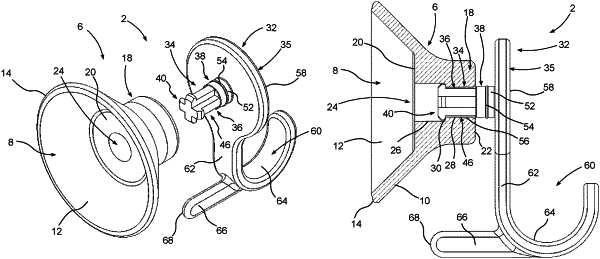
1. A valve-actuated suction apparatus, comprising:
an anchor member comprising a non-porous resilient material;
the anchor member comprising a flexible base seal member having a seal member outer side, a seal member inner side, and a seal member peripheral edge;
the seal member inner side being configured to form a substantially airtight seal with a surface to define a controlled pressure zone, the controlled pressure zone comprising a region located between the seal member inner side and the surface;
the anchor member further comprising an anchor member stem having a stem base end disposed on the base seal member and a stem free end spaced from the stem base end;
a vent port extending through the anchor member stem;
the vent port comprising having a first vent port section and a second vent port section, the first vent port section being disposed in relative proximity to the stem base end and the second vent port section being disposed in relative proximity to the stem free end;
a vent port internal shoulder defined at an outer end of the first vent port section, the vent port internal shoulder facing toward the stem base end;
a plunger valve operable to selectively seal and unseal the vent port;
the plunger valve comprising a plunger valve stem;
the plunger valve stem being slidably disposed in the vent port and slidable between a closed position of the plunger valve wherein the vent port is sealed and an open position of the plunger valve wherein the vent port is unsealed;
the plunger valve stem comprising a first valve stem section and a second valve stem section;
the first valve stem section comprising a valve stem stabilizer configured to block against the vent port internal shoulder in the open position in order to prevent removal of the plunger valve from the vent port during normal operation of the suction apparatus;
the first valve stem section further comprising an air bypass neck that resides at least partially in the first vent port section when the plunger valve is in the closed position, and extends through the second vent port section when the plunger valve is in the open position, the air bypass neck being configured to channel air through the second vent port section when the plunger valve is in the open position;
the second valve stem section comprising a vent port stopper configured to plug the second vent port section when the plunger valve is in the closed position in order to prevent a passage of air through the vent port;
the closed position of the plunger valve comprising the vent port stopper plugging the second vent port section;
the open position of the plunger valve comprising the vent port stopper being retracted from the second vent port section, the air bypass neck extending through the second vent port section to channel air therethrough, and the valve stem stabilizer engaging the vent port internal shoulder;
wherein, when the plunger valve is pushed into the closed position while the base seal member is pressed against the surface, the base seal member will flatten against the surface to establish and seal the controlled pressure zone, thereby rendering it airtight in order to maintain a negative pressure differential relative to an area of ambient pressure outside the controlled pressure zone; and
wherein, when the plunger valve is pulled out to the open position while the base seal member is attached to the surface, the base seal member will detach from the surface due to the controlled pressure zone being vented, thereby releasing the negative pressure differential relative to the area of ambient pressure outside the controlled pressure zone.
|