| CPC F16B 31/02 (2013.01) | 13 Claims |

|
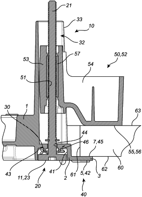
1. A threaded joint arrangement with visual and tactile indication of correct tightening force, the threaded joint arrangement comprising
a threaded fastener having a fastener shaft and a fastener head,
a biasing member,
a first object provided with a cavity recessed in a reference surface of the first object, wherein the cavity has a bottom surface provided with a through hole, and
a second object provided with a threaded hole,
wherein the through hole is aligned with the threaded hole,
wherein the threaded fastener is arranged such that the fastener shaft extends through the through hole and is in threaded engagement with the threaded hole of the second object,
wherein the biasing member is arranged in the cavity between the fastener head and the bottom surface of the cavity,
wherein the biasing member is configured to be compressed between the fastener head and the bottom surface of the cavity in response to rotation of the threaded fastener in a tightening direction,
wherein an alignment surface of the threaded joint arrangement is movable by rotation of the threaded fastener between a first position in which the alignment surface is positioned outside the cavity, a second position in which the alignment surface is flush with the reference surface and a third position in which the alignment surface is positioned inside the cavity, and
wherein the biasing member has a spring constant configured such that a tightening force of a predetermined level is obtained when the alignment surface is in the second position, wherein the alignment surface of the threaded joint arrangement extends in a plane parallel with the reference surface and wherein the alignment surface and the reference surface are mutually arranged such that the tightening force of the predetermined level is visually and tactilely determinable by observing and touching, respectively, the threaded joint arrangement and registering the flush relationship between the alignment surface and the reference surface.
|