| CPC F04D 29/4213 (2013.01) [F04D 17/10 (2013.01); F04D 25/08 (2013.01); F04D 29/4226 (2013.01); F04D 29/441 (2013.01); F04D 29/703 (2013.01); B60H 2001/00085 (2013.01); B60H 1/00471 (2013.01); F04D 17/162 (2013.01); F04D 29/424 (2013.01)] | 11 Claims |

|
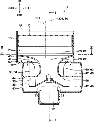
1. A centrifugal blower for an air conditioner, the centrifugal blower being configured to separately draw an inside air and an outside air at the same time, the centrifugal blower comprising:
a box defining an outside air introducing port through which the outside air is introduced into the box and an inside air introducing port through which the inside air is introduced into the box;
a filter configured to collect foreign matters in the air introduced into the box;
an impeller configured to rotate by a motor, the impeller being configured to draw the air having passed through the filter in an axial direction of the impeller and blow the air radially outward of the impeller;
a scroll casing surrounding the impeller, having a nose portion on an outer circumference of the scroll casing, and defining an air passage between the scroll casing and the impeller, the air passage having an area increasing from the nose portion in a circumferential direction;
an annular bell mouth disposed in a first end surface of the scroll casing in the axial direction, the annular bell mouth defining an inlet through which the air is drawn toward the impeller;
a partition wall configured to divide the air passage into an upper passage and a lower passage, the upper passage and the lower passage being arranged from a first end side of the air passage to a second end side of the air passage along the axial direction; and
a separation tube including:
an air introducing plate that is disposed in an area between the impeller and the filter to partially cover the impeller and that defines an air inlet portion; and
a tubular portion that extends from the air inlet portion through the impeller, wherein
the centrifugal blower is configured such that
a portion of the air flows through the filter toward the air introducing plate, flows into the air inlet portion, flows through the tubular portion, and then is discharged into the lower passage by the impeller, and
a portion of the air flows through the filter, flows through an area that is outside of the air introducing plate, flows through outside of the tubular portion, and is discharged into the upper passage by the impeller,
a virtual plane is defined as a plane that is parallel to a rotational axis of the impeller and an outer edge of the air introducing plate is on the virtual plane,
a passage through which air flows from the filter to the upper passage has a cross-section on the virtual plane that is divided by the separation tube into a first passage cross-section and a second passage cross-section,
the first passage cross-section is closer to the nose portion than the second passage cross-section is to the nose portion, and
the first passage cross-section is larger than the second passage cross-section.
|