| CPC F04D 27/003 (2013.01) [A47C 27/082 (2013.01); F04D 17/10 (2013.01); F04D 25/084 (2013.01); F04D 29/503 (2013.01)] | 15 Claims |

|
1. A built-in air pump for an inflatable product, comprising:
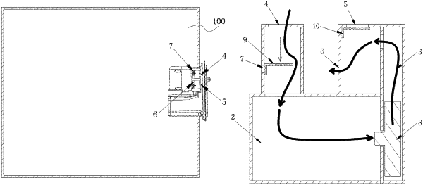
a first channel, a first air hole and a third air hole being formed in the first channel;
a second channel, a second air hole and a fourth air hole being formed in the second channel; and
a centrifugal fan, a suction end of the centrifugal fan abutting against the first channel, and an exhaust end of the centrifugal fan abutting against the second channel,
wherein the first air hole and the second air hole are configured to externally communicate with an outside of the inflatable product, and the third air hole and the fourth air hole are configured to internally communicate with an inner cavity of the inflatable product;
wherein the centrifugal fan is configured to start to operate, and the first air hole and the fourth air hole are configured to be opened and the second air hole and the third air hole are configured to be closed when inflation of the inflatable product is required, so that the air outside is sucked into the first channel through the first air hole by the centrifugal fan, and further pushed to the second channel and delivered to the inner cavity of the inflatable product through the fourth air hole by the centrifugal fan; the first air hole and the second air hole are further configured to be closed to prevent the air from leaking to the outside when inflation is completed, and
wherein the centrifugal fan is configured to start to operate, and the third air hole and the second air hole are configured to be opened and the first air hole and the fourth air hole are configured to be closed when deflation of the inflatable product is required, so that the air in the inner cavity of the inflatable product is sucked into the first channel through the third air hole by the centrifugal fan, and further pushed into the second channel and discharged to the outside through the second air hole by the centrifugal fan;
further comprising a control mechanism and a valve mechanism, the valve mechanism being controlled by the control mechanism to open or close the first air hole, the second air hole, the third air hole and the fourth air hole, wherein the valve mechanism includes a first movable valve and a second movable valve which are respectively slidable in a mounting sleeve, each of the movable valve includes a valve plate, a spring bearing and a side valve plate, the valve plate is sleeved with the respective mounting sleeve in a sliding way, the spring bearing is fixed to a bottom of the valve plate and located in the respective mounting sleeve, the side valve plate of each movable valve is respectively located on one side of the third air hole and the fourth air hole, and a spring is sleeved on the spring bearing of each movable valve and is adapted to elastically drive the respective valve plate to move upward to keep the first air hole and the second air hole closed.
|