|
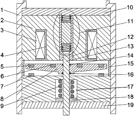
1. A permanent magnet-electromagnet synergistic coupling-based high-speed solenoid valve with a high dynamic response and a low rebound, comprising a shell, an iron core, an armature, a reset spring cavity and a valve rod, wherein a fixing nut and a clamp nut are arranged at a top and a bottom of the shell respectively, the iron core is installed in the shell and provided with an annular groove, a coil framework is embedded into the annular groove, a coil is wound around the coil framework, an axial center through hole is formed in a middle of the iron core, a spring limiting sleeve is installed in the axial center through hole, an armature and a reset spring cavity are sequentially formed below the iron core, the valve rod penetrates through the reset spring cavity and the armature, an upper portion of the valve rod is located in the spring limiting sleeve, a part of the valve rod, located in the reset spring cavity, is sleeved with an armature reset spring, an upper disc permanent magnet, a lower disc permanent magnet and a spring washer are arranged in the spring limiting sleeve, a giant magnetostrictor is installed between the upper disc permanent magnet and the lower disc permanent magnet, a first buffer spring is installed between the upper disc permanent magnet and the fixing nut, a second buffer spring is installed between the lower disc permanent magnet and the spring washer, and a buffer air gap is formed between the spring washer and the valve rod.
|
