| CPC F02K 9/95 (2013.01) [F02K 9/52 (2013.01); F02K 9/64 (2013.01)] | 18 Claims |

|
10. A rocket comprising:
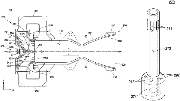
a fuel tank storing a fuel, an oxidizer tank storing an oxidizer, a rocket engine that generates a propulsion force by receiving the fuel and the oxidizer from the fuel tank and the oxidizer tank, and a mixing head assembly integrated with an igniter for igniting the rocket engine,
wherein the rocket engine comprises a combustion chamber and the mixing head assembly, which is disposed at one side of the combustion chamber and is integrated with the combustion chamber, and the mixing head assembly further comprises:
a head including an injection surface communicating with an inlet of the combustion chamber, and an internal space located inside the head;
a first manifold, which is disposed inside a first portion of the internal space of the head and into which an oxidizer flows into an empty space inside the first manifold;
a second manifold, which is disposed inside a second portion of the internal space of the head and into which a fuel flows into an empty space inside the second manifold;
an igniter chamber disposed inside a third portion of the internal space of the head;
a first flow path configured to supply the oxidizer from the first manifold to the igniter chamber;
a second flow path configured to supply the fuel from the second manifold to the igniter chamber;
a plurality of injectors extending upward from the injection surface through the internal space and contacting an inner upper surface of the head, the plurality of injectors communicating with the first manifold and the second manifold, respectively, and
a partitioning wall partitioning the internal space of the head into the first manifold and the second manifold, the partitioning wall extending radially outward around the igniter chamber and contacting a radially inner surface of the head,
wherein each one of the plurality of injectors has a pillar shape parallel to a center axis of the combustion chamber and are exposed to the empty spaces of the first manifold and the second manifold,
wherein each one of the plurality of the injectors comprises:
a first part having a hollow cylindrical shape with a first diameter;
a first injection path formed inside the first part;
a plurality of first injection holes formed on an upper outer peripheral surface of the first part and communicating with the first manifold and the first injection path;
a second part formed on a lower outer peripheral surface of the first part, the second part having a second diameter that is greater than the first diameter of the first part;
a second injection path formed inside the second part;
a plurality of second injection holes formed on an upper surface of the second part and communicating with the second manifold and the second injection path, and
wherein the combustion chamber and the mixing head assembly are integrally formed by additive manufacturing through 3D printing.
|