| CPC F02K 3/06 (2013.01) [F02C 3/04 (2013.01); F02C 7/04 (2013.01); F02C 7/36 (2013.01); B64D 27/12 (2013.01); B64D 2033/0286 (2013.01); F05D 2220/32 (2013.01); F05D 2240/24 (2013.01); F05D 2260/80 (2013.01); Y02T 50/60 (2013.01)] | 12 Claims |
|
1. A gas turbine engine for an aircraft comprising:
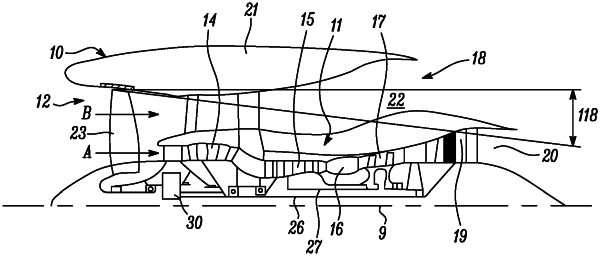
an engine core comprising a turbine, a compressor, and a core shaft connecting the turbine to the compressor, and a core exhaust nozzle having a core exhaust nozzle exit, the core exhaust nozzle having a core exhaust nozzle pressure ratio calculated using total pressure at the core exhaust nozzle exit, the engine core having a core length;
a fan located upstream of the engine core, the fan comprising a plurality of fan blades, the fan blades together defining a fan face having a fan face area;
a nacelle surrounding the gas turbine engine, the nacelle comprising an inner surface at least partly defining a bypass duct located radially outside of the engine core;
the bypass duct comprising a bypass exhaust nozzle having a bypass exhaust nozzle exit, the bypass exhaust nozzle having a bypass exhaust nozzle pressure ratio calculated using total pressure at the bypass exhaust nozzle exit; and
a bypass duct outlet guide vane extending radially across the bypass duct between an outer surface of the engine core and the inner surface of the nacelle,
wherein the bypass duct outlet guide vane extends between a radially inner tip and a radially outer tip and has a leading edge and a trailing edge relative to a direction of gas flow through the bypass duct,
an outer wall axis is defined joining the radially outer tip of the trailing edge of the bypass duct outlet guide vane and a rearmost tip of the inner surface of the nacelle, wherein the outer wall axis lies in a longitudinal plane containing a centreline of the gas turbine engine,
an outer bypass duct wall angle is defined as an angle between the outer wall axis and the centreline,
and the outer bypass duct wall angle is in a range from −15 to −2.5 degrees, and
wherein the bypass duct is configured with a bypass exhaust nozzle that has an inner radius, and an inner bypass to fan ratio of:
is in a range from 0.5 to 0.6, wherein the inner radius of the bypass exhaust nozzle is a radial distance between the centreline of the gas turbine engine and an outer surface of the engine core at an axial position of the rearmost tip of the nacelle, and the inner radius of the bypass exhaust nozzle is used to calculate the inner bypass to fan ratio, and
wherein a bypass to core ratio of:
 is configured to be in the range from 1.1 to 2 under cruise conditions
and an engine area ratio of:
 is in a range from 2 to 3, and the fan tip radius is in a range from 155 to 200 cm.
|