| CPC F02C 7/32 (2013.01) [F01D 15/10 (2013.01); F02C 7/268 (2013.01); H02K 1/185 (2013.01); H02K 7/1823 (2013.01); F05D 2220/323 (2013.01); F05D 2220/76 (2013.01); F05D 2230/60 (2013.01); F05D 2260/85 (2013.01)] | 19 Claims |

|
1. A gas turbine engine, comprising:
an engine frame defining an inner radial surface;
a shaft rotatably mounted inside the engine frame along a longitudinal axis;
an electric machine comprising:
a rotor coupled to the shaft; and
a stator coupled to the engine frame; and
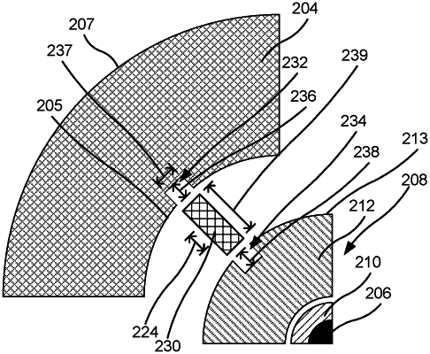
two or more positioning keys configured to substantially fix the stator relative to the engine frame,
wherein the engine frame comprises an inlet fluid passage and an outlet fluid passage, each extending to a portion of the inner radial surface of the engine frame,
wherein the portion of the inner radial surface of the engine frame is spaced from an outer radial surface of the stator to form an annular fluid passage around the stator,
wherein the annular fluid passage is configured to direct a cooling fluid around the stator to remove heat from the stator, and
wherein each of the two or more positioning keys includes at least one of a cutout or a window configured to permit flow of the cooling fluid through the respective positioning key.
|