| CPC F02C 7/32 (2013.01) [F01D 15/10 (2013.01); F02C 7/36 (2013.01); F05D 2220/323 (2013.01); F05D 2220/76 (2013.01); F05D 2260/40 (2013.01)] | 13 Claims |

|
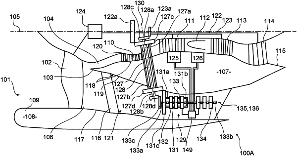
1. A bypass turbine engine comprising, from upstream to downstream in an axial direction of gas flow, a fan and a splitter nose from which originate a primary stream flow channel, called a primary flow path, and a secondary stream flow channel, called a secondary flow path, which surrounds the primary flow path, the turbine engine further comprising:
a fixed casing comprising an arm which extends radially, relative to a longitudinal axis, in the secondary flow path,
a first shaft, called a low pressure shaft, designed to rotate relative to the casing about the longitudinal axis oriented in the axial direction of the gas flow,
a second shaft, called a high pressure shaft, designed to rotate relative to the casing around the low pressure shaft, the high pressure and low pressure shafts being concentric,
at least one accessory designed to be driven by a motor powered with electrical energy,
an upper portion via which the turbine engine is intended to be attached to an aircraft,
an opposite lower portion in a vertical direction orthogonal to the longitudinal axis, the arm extending generally vertically, in the lower portion, in the secondary flow path,
the turbine engine being characterised in that it further comprises:
a first intermediate shaft designed to draw mechanical power from the low pressure shaft,
a second intermediate shaft designed to draw mechanical power from the high pressure shaft,
an electrical energy generator assembly housed in the arm and coupled, on the one hand, to the first intermediate shaft and, on the other hand, to the second intermediate shaft, so as to receive the mechanical power from the first intermediate shaft, on the one hand, and the mechanical power from the second intermediate shaft, on the other hand, the generator assembly being further designed to convert the mechanical power received from the first and second intermediate shafts into electrical energy in order to power the motor(s) driving the accessory or accessories, the electrical energy powering the motor(s) driving the accessory or accessories thus originating simultaneously from the mechanical power drawn from the low pressure shaft and the mechanical power drawn from the high pressure shaft,
wherein the generator assembly comprises:
a first drive shaft designed to draw the mechanical power from the first intermediate shaft and to rotate relative to the casing about a first drive axis,
a second drive shaft designed to draw the mechanical power from the second intermediate shaft and to rotate relative to the casing about a second drive axis, the first and second drive shafts being coaxial and each designed to rotate, in an opposite direction of rotation, about the first and second drive axes then coincident,
one or more first alternators each comprising an inductor rotor mounted secured in rotation with one of the first and second drive shafts about the first and second drive axes and an induced rotor mounted secured in rotation with the other of the first and second drive shafts about the first and second drive axes,
one or more second alternators each comprising an inductor rotor mounted secured in rotation, about the first and second drive axes, with that of the first and second drive shafts which is surrounded by the other of the first and second drive shafts, and an induced stator which is fixed relative to the inductor rotor of said second alternator,
wherein the first and second drive axes are oriented generally in the axial direction of gas flow,
wherein at least a portion of the one or more second alternators is located downstream of an entirety of the one or more first alternators in the axial direction of the gas flow.
|