| CPC F02C 7/18 (2013.01) [F23R 3/16 (2013.01); F23R 3/26 (2013.01); F23R 2900/03044 (2013.01)] | 13 Claims |

|
1. A combustor for use in a gas turbine engine, the combustor enclosing a combustion chamber having a combustion area, wherein the combustor comprises:
a combustion liner having an inner surface defining the combustion chamber and an outer surface opposite the inner surface, the combustion liner including a primary aperture extending from the outer surface to the inner surface through the combustion liner, the outer surface of the combustion liner being oriented relative to a first airflow path such that airflow in the first airflow path separates from the outer surface of the combustion liner;
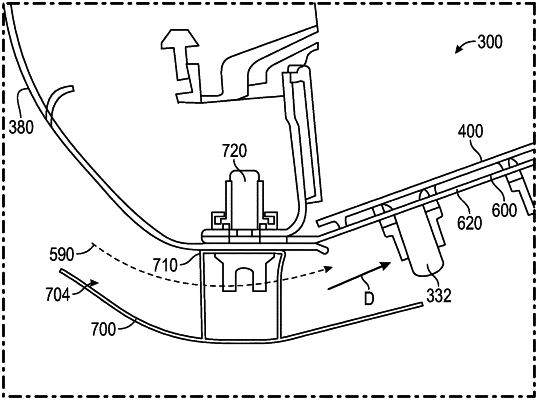
a first fairing secured to the combustor, the first fairing defining a first air passageway between the outer surface of the combustion liner and the first fairing, and a second air passageway between the first fairing and a combustor casing, the first fairing being located between the first air passageway and the second air passageway, the first air passageway extending from an inlet to an exit, the first fairing being configured to redirect the airflow in the first airflow path such that the airflow exits the first air passageway and the first fairing parallel to the outer surface of the combustion liner, the first air passageway being located completely outside the combustion chamber, such that the inlet of the first air passageway and the exit of the first air passageway are located completely outside the combustion chamber, and
a heat shield panel interposed between the inner surface of the combustion liner and the combustion area, the heat shield panel having a first surface and a second surface opposite the first surface, the second surface being oriented towards the inner surface of the combustion liner, and the heat shield panel is separated from the combustion liner by an impingement cavity,
wherein the first fairing is secured to the combustor through an attachment mechanism, the attachment mechanism securing the combustion liner and a cowl to the combustor, and
wherein the combustion liner, the heat shield panel, and the first fairing are annular and concentric,
and the first fairing is secured to the combustor proximate a forward end of the combustor, and
wherein a forward end and a rearward end of the first fairing each extend from a central portion of the first fairing, the central portion of the first fairing being generally aligned with a point of securement of the first fairing to the attachment mechanism, the forward end and the rearward end of the first fairing each being radially displaced from the central portion of the first fairing.
|