| CPC F01N 1/065 (2013.01) [F01N 1/22 (2013.01); F01N 13/08 (2013.01); F01N 13/10 (2013.01); G10K 11/22 (2013.01); F01N 1/20 (2013.01)] | 23 Claims |

|
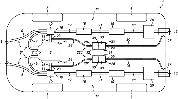
1. A vehicle comprising:
an internal combustion engine having at least one cylinder, the internal combustion engine comprising an exhaust manifold for collecting exhaust gases expelled from the at least one cylinder;
an exhaust system configured to channel exhaust gases along a flow path from the exhaust manifold to at least one exhaust outlet, the exhaust system comprising at least one exhaust component configured to act on exhaust gases flowing though the exhaust component and causing an alteration to engine-generated sound pulses passing through the exhaust component; and
a sound bypass device comprising a sound inlet port at a first location on the exhaust system before a first exhaust component along the flow path and a sound outlet port at a second location on the exhaust system after the first exhaust component along the flow path, the sound bypass device being configured to transmit engine-generated sound pulses from the sound inlet port to the sound outlet port whilst preventing flow of exhaust gases from the sound inlet port to the sound outlet port, the sound bypass device further comprising a sound transmission device, the sound transmission device comprising:
a sound inlet port being connected to the sound inlet port of the sound bypass device and a sound outlet port being connected to the sound outlet port of the sound bypass device, the sound transmission device being configured to transmit engine-generated sound pulses from the sound inlet port of the sound bypass device to the sound outlet port of the sound bypass device whilst preventing the flow of exhaust gases from the sound inlet port of the sound bypass device to the sound outlet port of the sound bypass device; and
a diaphragm housed in a chamber connected to the first sound inlet port of the sound transmission device, the diaphragm having a perimeter running around an exterior edge of the diaphragm, the diaphragm being connected across the chamber and configured such that, in response to engine-generated sound pulses being conducted from the sound inlet port of the sound transmission device into the chamber, the diaphragm vibrates so as to transmit the engine-generated sound pulses across the diaphragm from a first side of the chamber at which the sound inlet port of the sound transmission device is located to a second side of the chamber at which the sound outlet port of the sound transmission device is located, the chamber being divided into a first volume, to the first side of the chamber, and a second volume, to the second side of the chamber, the first volume being defined by the diaphragm, a first end wall and a first flexible membrane that seals around the perimeter of the diaphragm and connects to the first end wall to enclose the first volume, the second volume being defined by the diaphragm a second end wall and a second flexible membrane that seals around the perimeter of the diaphragm and connects to the second end wall to enclose the second volume.
|