| CPC F01D 5/225 (2013.01) [F01D 5/16 (2013.01); F01D 11/08 (2013.01); F05D 2220/323 (2013.01); F05D 2230/80 (2013.01); F05D 2240/24 (2013.01)] | 8 Claims |
|
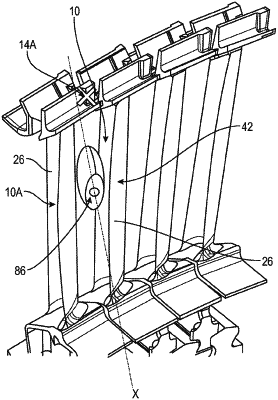
1. A method of refitting vanes shrouds of a rotor wheel in an aircraft turbomachine, the rotor wheel comprising a disc bearing vanes that each comprise a blade extending between a root and a shroud, the shroud of each vane comprising lateral edges comprising shapes complementary to the lateral edges of the shrouds of the adjacent vanes, the lateral edges of the shrouds being interlocked in engagement with one another such that anti-wear coatings of these edges contact each other in a desired interlocking engagement position, and at least one of the lateral edges of at least one of the shrouds being configured to be disengaged from the lateral edge of an adjacent shroud in an undesired disengagement position, the method comprising, when such an undesired disengagement position is detected,
a step of inserting a re-engagement device into the turbomachine, and
a step of moving the at least one shroud from this undesired position to the desired interlocking engagement position by bearing on and exerting a force on the vane or each vane whose shroud is disengaged,
the re-engagement device comprising an endoscope that includes at least two clamps configured to cooperate with the blade or the shroud of one vane to perform the moving step, wherein the clamps are each configured to grip a leading edge and/or a trailing edge of the blade, or even of an adjacent blade, during the moving step, a first clamp being configured to grip a leading edge of the blade, and a second clamp being oriented in a different direction from that of the first clamp and configured to grip a trailing edge of an adjacent blade.
|