| CPC F01D 5/189 (2013.01) [F01D 5/147 (2013.01); F01D 5/16 (2013.01); F01D 5/20 (2013.01); F01D 25/12 (2013.01); F01D 25/06 (2013.01); F05D 2260/201 (2013.01); F05D 2260/96 (2013.01)] | 18 Claims |

|
1. A turbine airfoil comprising:
an airfoil body formed by an outer wall, the outer wall comprising a pressure side wall and a suction side wall joined at a leading edge and at a trailing edge,
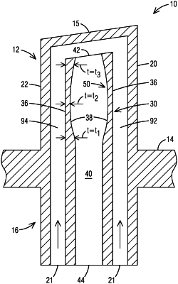
a flow displacement element that is hollow positioned in an interior portion of the airfoil body and extending along a span-wise extent thereof, the flow displacement element defining an inactive cavity therewithin,
wherein the flow displacement element is spaced from the pressure side wall and the suction side wall to respectively define a first near-wall cooling flow channel and a second near-wall cooling flow channel,
wherein the flow displacement element comprises an outer surface facing said near-wall cooling flow channels and an inner surface facing the inactive cavity,
wherein the inner surface facing the inactive cavity comprises features configured to influence a mass and/or stiffness of the turbine airfoil, to thereby produce a predetermined modal frequency response of the turbine airfoil,
wherein said features are realized by providing a contour to the inner surface of the flow displacement element such that the flow displacement element has a variable wall thickness.
|