| CPC F01D 5/187 (2013.01) [F01D 5/087 (2013.01); F05D 2240/307 (2013.01); F05D 2260/20 (2013.01); F05D 2260/201 (2013.01); F05D 2260/232 (2013.01)] | 20 Claims |

|
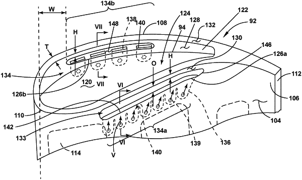
1. An engine component for a turbine engine having a working airflow separated into a cooling airflow and a combustion airflow, the engine component comprising:
an outer wall defining an interior and having an outer surface over which flows the combustion airflow, the outer surface defining a first side and a second side extending between an upstream edge and a downstream edge to define a streamwise direction and extending between a root and a tip to define a radial direction;
a tip wall spanning the first side and the second side to close the interior at the tip;
a tip rail extending from the tip wall and having an inner tip rail surface, which in combination with the tip wall, at least partially bounds a region defining a plenum, the tip rail having an outer tip rail surface extending from at least one of the first or the second sides, and radially terminating in an upper tip rail surface connecting the inner tip rail surface and the outer tip rail surface;
a tip rim formed in at least one of the outer surface or the inner tip rail surface and spaced from the upper tip rail surface in the radial direction,
at least one cooling conduit provided in the interior;
a trench outlet defining at least a portion of the tip rim; and
multiple cooling passages formed in the outer wall and fluidly coupling the at least one cooling conduit to the trench outlet, wherein the multiple cooling passages terminate in corresponding passage outlets, which are merged together to form the trench outlet.
|