| CPC E21B 17/02 (2013.01) [E02D 5/385 (2013.01); E02D 11/00 (2013.01); E21B 7/20 (2013.01); E21B 7/205 (2013.01); E21B 7/26 (2013.01)] | 3 Claims |

|
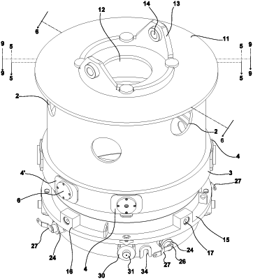
1. A locking and rotating device for tubular casing elements the device includes three cylindrical components with a circular section, in a coaxial and nested arrangement,
said three cylindrical components include:
a) an upper cylindrical element (1) is provided on its circumferential surface with circular holes (2) and a collar (3) below said circumferential surface, said collar includes four first seats covered by a flange (4) and two second seats (4′) and pins (5) each formed with a polygonal cross-section with rounded corners and a circular head (6), said pins and circular head are held in place inside said four seats by screws (7); the collar (3) is provided with two other seats (4′) each including an intercepting pin (5′),
b) a central cylindrical element (9), including four rectangular slots (8) and two quadrangular slots (10) defined on its circumferential surface, and a collar (15) defining four seats (16) for holding pins (17) and pockets (33) wherein the two quadrangular slots (10) are configured to be engaged by the intercepting pin (5′), when the central cylindrical element (9) is placed inside and coaxial with the upper cylindrical element (1);
c) a lower cylindrical element (19) including a lateral circumferential surface provided with a series of holes, and two slots (23, 23′) equal and side by side, each shaped with a crenellation, to form an area limiting the movement of the pins (5); said lower cylindrical element (19) further includes a circumferential channel (18) and a coupling surface configured for connection with a male joint of a lining tube (35), said coupling surface includes four holes including quick-release couplings (24) having a bush (25), pin (26), operating handle (27) and transverse pin (28) able to move on an eccentric guide (29); said coupling surface further includes bushes (30) configured to hold truncated-conical section pins (31), each one of the truncated-conical section pins includes a vertical pin (32) configured to be inserted and to slide into one of the pockets (33) defined on the collar (15) of the central cylindrical element (9);
wherein the ends of pins (17) intercept and fit into the circumferential channel (18) when the lower cylindrical element (19) is inside and coaxial with the cylindrical element (9).
|