| CPC E06C 1/18 (2013.01) [E06C 1/10 (2013.01); E06C 1/22 (2013.01); E06C 1/32 (2013.01)] | 17 Claims |

|
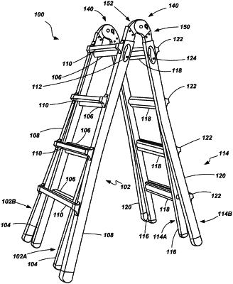
1. A method of forming a ladder, the method comprising:
providing a first rail assembly having a first rail, a second rail and a first plurality of rungs extending between and coupled to the first rail and the second rail;
providing a second rail assembly having a third rail and a fourth rail;
coupling a first hinge mechanism between the first rail and the third rail;
coupling a second hinge mechanism between the second rail and the fourth rail;
configuring at least one of the first and second hinge mechanisms to include:
a first hinge assembly having at least one hinge plate,
a second hinge assembly having at least one hinge plate, the first hinge assembly being rotatably coupled to the second hinge assembly,
an adjustment mechanism configured to selectively permit and prohibit relative rotation of the first hinge assembly and the second hinge assembly,
configuring the adjustment mechanism to include:
a lock plate biased in a first direction along a first axis, the lock plate having a first portion configured to engage at least one recess formed on a periphery of the at least one hinge plate of the second hinge assembly, the lock plate having an opening formed in a surface thereof,
a retainer being biased in a second direction along a second axis and toward contact with the lock plate, the retainer having a protrusion configured for selective engagement with the opening in the lock plate, and
a release structure configured to be displaced along the first axis such that a portion of the release structure becomes interposed between the retainer and the lock plate to displace the retainer opposite the second direction and displacing the protrusion from the opening of the lock plate such that no part of the retainer is in the opening of the lock plate.
|