| CPC E05C 17/56 (2013.01) [E05F 5/06 (2013.01)] | 11 Claims |

|
11. A magnetic doorstop and door holder comprising:
a hinge pin doorstop body having a first end and an opposing second end;
a hinge pin receiving aperture disposed at the first end of the hinge pin doorstop body, the hinge pin receiving aperture configured to receive a hinge pin of a hinge of a door;
a first leg having a proximal end and a distal end, the proximal end connected to the second end of the hinge pin doorstop body, and the distal end extending outward from the hinge pin doorstop body;
an engagement member disposed at the second end of the hinge pin doorstop body adjacent the proximal end of the first leg;
a second leg having a proximal end and a distal end, the proximal end adjustably received in the engagement member, and the distal end extending outward from the engagement member;
a first bumper attached to the distal end of the first leg;
a second bumper attached to the distal end of the second leg;
a first magnet attached to the first bumper;
a second magnet attached to the second bumper;
a first ferromagnetic structure configured for attachment to the door, the first ferromagnetic structure comprising one or more materials that are magnetically attracted to the first magnet; and
a second ferromagnetic structure configured for attachment to a door frame, door jamb, wall, or other entryway structure to which the hinge is attached, the second ferromagnetic structure comprising one or more materials that are magnetically attracted to the second magnet,
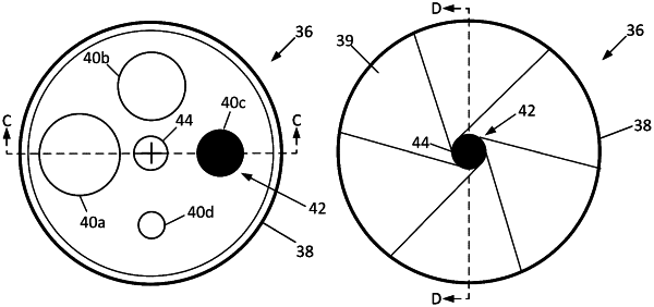
wherein one or both of the first ferromagnetic structure and the second ferromagnetic structure comprise a magnetic shunt assembly that includes a housing containing a rotatable top plate in which a plurality of apertures of different sizes are disposed, and a third magnet fixedly attached to the housing in proximity to the rotatable top plate, wherein a force of magnetic attraction between the magnetic shunt assembly and the first or second magnet is adjustable based on selection of one of the plurality of apertures to be aligned with the third magnet.
|