| CPC E04H 15/50 (2013.01) [E04F 10/02 (2013.01); E04H 15/28 (2013.01); E04H 15/34 (2013.01); E04H 15/58 (2013.01)] | 4 Claims |

|
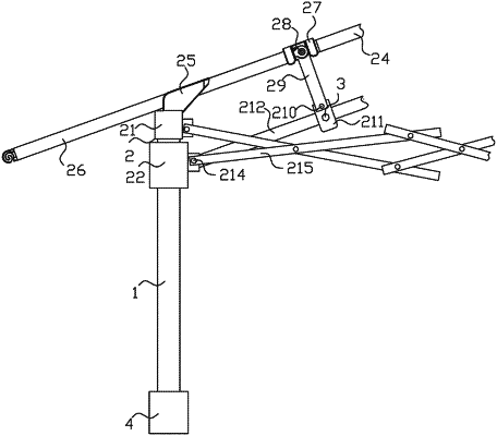
1. A connection assembly for an overhanging canopy, comprising a support column (1) and a connection adjustment mechanism (2), wherein the connection adjustment mechanism (2) is arranged on the support column (1);
the connection adjustment mechanism (2) comprises a fixed block (21) and a movable block (22), the fixed block (21) is arranged on the top of the support column (1), and a mounting block (23) is arranged on the rear side of the top of the fixing block (21), a connecting rod (24) is arranged on the inner wall of the mounting block (23), and the right side of the connecting rod (24) is configured to penetrate the mounting block (23) and extend to the outside thereof, a limiting frame (25) is arranged on the front of the mounting block (23), an adjusting rod (26) is arranged on the left side of the limiting frame (25), a positioning sleeve (27) is arranged on the right side of the surface of the connecting rod (24), and the right end of the adjusting rod (26) is configured to sequentially penetrate the limiting frame (25) and the positioning sleeve (27) from left to right and extend to the interior of the positioning sleeve (27), the right side of the adjusting rod (26) is configured to movably connect with the driving block (29) through the movable rotating shaft (28), and a top of the driving block (29) is configured to penetrate the positioning sleeve (27) and extend to the outside thereof, a first rotating shaft (210) is arranged on a bottom of the driving block (29), a surface of the first rotating shaft (210) is movably connected with a mounting sleeve (211), and a mounting rod (212) is arranged at right side of the mounting sleeve (211), the left end of the mounting rod (212) is configured to penetrate the mounting sleeve (211) and extend to the outside thereof, the movable block (22) is slidably connected to the surface of the support column (1), the back side of the right side of the movable block (22) is movably connected with the mounting rod (212) through the second rotating shaft (213), third rotating shafts (214) are arranged on the back and right side of the fixed block (21) and the back and right side of the movable block (22), and the two third rotating shafts (214) on the same side are movably connected by folding telescopic rods (215);
wherein the bottom of the positioning sleeve (27) is configured to be in an open state;
wherein the surface of the adjusting rod (26) is configured to be in contact with the inner wall of the positioning sleeve (27);
wherein the front surface of the mounting sleeve (211) is threadedly connected to the mounting rod (212) through a fixing bolt (3).
|