|
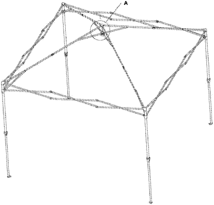
1. A center lock structure, comprising: a chassis, rotary sliding sleeve and a center rod, a top of the rotary sliding sleeve is circumferentially and slidably connected with the chassis, and the center rod is extended into the rotary sliding sleeve along the top of the chassis, a top of the chassis is provided with multiple sets of rib fixing members; an elastic member is provided at one side on a bottom of the center rod, the elastic member is exposed outside the center rod when there is no external force, and the elastic member is concealed in the center rod when squeezed by an external force; the chassis and the rotary sliding sleeve are respectively provided with a first through hole and a second through hole that make the elastic member concealed in the center rod, and a top of the first through hole is provided with a funnel through hole with an inner diameter gradually increasing from bottom to top, the second through hole is provided with an elastic member accommodating groove when the rotary sliding sleeve rotates to make a side wall of the accommodating groove press the elastic member into the center rod, the center rod and the rotary sliding sleeve are unlocked.
|
