| CPC E04F 15/02038 (2013.01) [E04F 15/107 (2013.01); F16B 5/0056 (2013.01); E04F 15/02033 (2013.01); E04F 2201/0138 (2013.01); E04F 2201/0146 (2013.01); E04F 2201/0176 (2013.01)] | 13 Claims |

|
1. A floor panel for forming a floor covering, wherein the floor panel has a first pair of mutually opposing edges and a second pair of mutually opposing edges;
wherein the first pair of mutually opposing edges comprises coupling parts which allow two of such floor panels to be coupled together, and
wherein these coupling parts have the following features:
the coupling parts comprise a horizontally active interlock system which, in a coupled state of two of such floor panels, realizes a lock in the plane of the floor panels perpendicularly to the edges concerned;
the coupling parts also comprise a vertically active interlock system which, in a coupled state of two of such floor panels, realizes a lock transversely to a plane of the floor panels;
the coupling parts are configured such that two of such panels can be coupled together at these edges by means of a rotational movement;
wherein the second pair of mutually opposing edges also comprises coupling parts on both edges, which allow two of such floor panels to be coupled together and wherein these coupling parts have the following features:
the coupling parts comprise a horizontally active interlock system which, in a coupled state of two of such floor panels, realizes a lock in the plane of the floor panels perpendicularly to the edges concerned;
the coupling parts also comprise a vertically active interlock system which, in a coupled state of two of such floor panels, realizes a lock transversely to the plane of the floor panels;
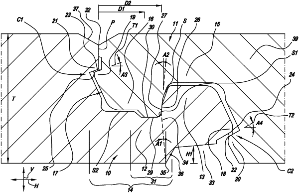
the horizontally active interlock system of the second pair of edges is at least formed by an upwardly pointing bottom hook-shaped part which is situated on one of said two edges, and a downwardly pointing top hook-shaped part which is situated on the opposite edge,
wherein the bottom hook-shaped part consists of a lip with an upwardly pointing locking element which proximally thereto defines a female part in the form of a recess, while the top hook-shaped part consists of a lip with a downwardly pointed locking element which forms a male part;
the coupling parts are configured such that two of such floor panels can be coupled together at their respective edges by means of a downward movement of the one floor panel relative to the other;
the vertically active interlock system comprises vertically active locking parts which, by means of respective contact faces, define at least a first locking zone and a second locking zone,
wherein said first locking zone comprises a first locking part formed on a distal surface of the male coupling part, and cooperating therewith a second locking part of the female part, and said second locking zone comprises a third locking part on a distal surface of said lip of the bottom hook-shaped part, and cooperating therewith a fourth locking part of the floor panel coupled thereto;
wherein the horizontally active interlock system of the second pair of edges comprises contact faces formed between the upwardly pointing locking element and the downwardly pointing locking element,
wherein these contact faces extend from bottom to top in a direction away from said first locking zone; and
the upwardly pointed locking part has a recess on its underside,
wherein a theoretical line between a proximate-most located point of said recess and the lowest point of the contact faces forms an angle with the vertical from 0° to 35°;
wherein the vertically active interlock system furthermore comprises contact faces between the downwardly pointing locking element and the lip of the bottom hook-shaped part,
wherein the contact faces are only situated on a half of said female coupling part which lies closest to the upwardly pointing locking element;
wherein the contact faces of the vertically active interlock system are situated on a part of the female coupling part which is situated at a distance from an upper edge of the panel edge with the female coupling part,
wherein this distance is at least 20 percent of a thickness of the floor panel.
|