| CPC D04H 1/736 (2013.01) [D01G 15/04 (2013.01); D01G 15/36 (2013.01); D01G 15/46 (2013.01)] | 8 Claims |

|
1. A method for producing nonwovens in a drylaid process in which fibres travel in a travelling direction, in an apparatus comprising:
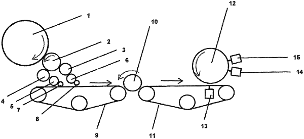
a card drum (1) that is rotatable in a first direction of rotation and at a first circumferential rotational speed by a first driving means, to thereby produce a fibre web in the process, wherein the apparatus further comprises, immediately downstream of the card drum (1) in the direction in which the fibres travel in the apparatus, a transfer cylinder (2) that is rotatable in a second direction of rotation, opposite to the first direction of rotation, and at a second circumferential rotational speed by a second rotation means, the second circumferential rotational speed being greater than the first circumferential rotational speed, the transfer cylinder (2) having, on a periphery, a covering (G) comprising a plurality of teeth (16) that are angled with respect to a radius of the transfer cylinder (2) and are oriented in the second direction of rotation, and, the apparatus further comprising immediately downstream of the transfer cylinder (2), a system that comprises, immediately sequentially in a travelling direction, at least one doffer (3, 4), at least one condenser (5, 6), at least one stripper roll (7, 8), a first endless conveyor belt (9) with an upper side, a suction drum (10), and a second endless conveyor belt (11) with an upper side, the suction drum (10) being adjacent to the upper side of each of the first and second conveyor belts (9, 11) and ensuring the fibres pass from the first conveyor belt to the second conveyor belt, and the apparatus further including a water-jet consolidation cylinder (12) adjacent to the upper side of the second endless conveyor belt (11),
wherein the apparatus is operated at the following speed ratios:
a ratio of a circumferential speed of the at least one doffer (3, 4) to a circumferential speed of the transfer cylinder (2) is between 0.10 and 0.20;
a ratio of a circumferential speed of the at least one condenser (5, 6) to the circumferential speed of the at least one doffer (3, 4) is between 0.35 and 0.55;
a ratio of a circumferential speed of the at least one stripper roll (7, 8) to the circumferential speed of the at least one condenser (5, 6) is between 1.50 and 1.75;
a ratio of a speed of the first endless conveyor belt (9) to the circumferential speed of the at least one stripper roll (7, 8) is between 0.95 and 1.10;
a ratio of a circumferential speed of the suction drum (10) to the speed of the first endless conveyor belt (9) is between 0.70 and 0.90;
a ratio of a circumferential speed of the water-jet consolidation cylinder (12) to a speed of the second endless conveyor belt (11) is between 0.75 and 1.05; and
a ratio of a speed of the second endless conveyor belt (11) to the circumferential speed of the suction drum (10) is between 0.70 and 0.90, wherein there is a distance between the at least one water-jet consolidation cylinder (12) and the second endless conveyor belt (11) of between 2 and 15 millimeters (mm).
|