| CPC B65D 19/16 (2013.01) [B65D 85/64 (2013.01); B65D 2519/00029 (2013.01); B65D 2519/00064 (2013.01); B65D 2519/00164 (2013.01); B65D 2519/00169 (2013.01); B65D 2519/00174 (2013.01); B65D 2519/00273 (2013.01); B65D 2519/00293 (2013.01); B65D 2519/00323 (2013.01); B65D 2519/00333 (2013.01); B65D 2519/00502 (2013.01); B65D 2519/00592 (2013.01); B65D 2519/00611 (2013.01); B65D 2519/00646 (2013.01); B65D 2519/00661 (2013.01); B65D 2519/00721 (2013.01); B65D 2519/00925 (2013.01)] | 19 Claims |

|
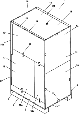
1. A collapsible pallet casing assembly (1) configured to be used as a shipping crate for bulky objects, comprising:
a pallet (2) provided with an upper loading surface (3) configured to form a bottom of the pallet casing assembly (1) in an erected state thereof and further provided with a frame structure enclosing the loading surface (3) on a rear side and lateral sides thereof by a vertical rear frame wall (4) and vertical first (6) and second (7) lateral frame walls at a rear edge (5) and first (8) and second (9) opposite lateral edges of the pallet (2), respectively,
a rear casing wall (10) comprising a lower rear wall section (11) hingedly connected at a lower end to the rear frame wall (4) to be foldable to a position on top of the loading surface (3) in a collapsed state of the pallet casing assembly (1), and an upper rear wall section (12) hingedly connected to an upper end of said lower rear wall section (11) to be foldable to a position on top of the lower rear wall section (11) in said collapsed state,
a top casing wall (14) comprising a top wall section (15) hingedly connected at a rear end to an upper end of the upper rear wall section (12) to be foldable to a position on top of the upper rear wall section (12) in said collapsed state,
a first lateral casing wall (17) comprising
a lower first lateral wall section (18) configured to rest on the first lateral frame wall (6) in said erected state and hingedly connected at a rear end to a first lateral end (20) of the lower rear wall section (11) to be foldable to a position overlapping the lower rear wall section (11) to be placed between the lower rear wall section (11) and the loading surface (3) in said collapsed state, and
an upper first lateral wall section (19) configured to rest on an upper end of the lower first lateral wall section (18) in said erected state and hingedly connected at an upper end to a first lateral end (21) of the top wall section (15) to be foldable to a position overlapping the top wall section (15) to be placed between the top wall section (15) and the upper rear wall section (12) in said collapsed state,
a second lateral casing wall (22) comprising
a lower second lateral wall section (23) configured to rest on the second lateral frame wall (7) in said erected state and hingedly connected at a rear end to a second lateral end (25) of the lower rear wall section (11) to be foldable to a position overlapping the lower first lateral wall section (18) to be placed between the lower first lateral wall section (18) and the loading surface (3) in said collapsed state, and
an upper second lateral wall section (24) configured to rest on an upper end of the lower second lateral wall section (23) in said erected state and hingedly connected at an upper end to a second lateral end (26) of the top wall section (15) to be foldable to a position overlapping the upper first lateral wall section (19) to be placed between the upper first lateral wall section (19) and the upper rear wall section (12) in said collapsed state, wherein
the lower rear wall section (11) has a width which is smaller than the distance between the first (6) and second (7) lateral frame walls,
the first lateral end (20) of the lower rear wall section (11) is located at a distance from the first lateral frame wall (6) in said erected state,
the second lateral end (25) of the lower rear wall section (11) is located at a distance from the second lateral frame wall (7) in said erected state,
the lower first lateral wall section (18) is hingedly connected to the first lateral end (20) of the lower rear wall section (11) by a first link element (27) connected at a first end to the rear end of the lower first lateral wall section (18) and pivotably connected at an opposite second end to the first lateral end (20) of the lower rear wall section (11), and
the lower second lateral wall section (23) is hingedly connected to the second lateral end (25) of the lower rear wall section (11) by a second link element (28) connected at a first end to the rear end of the lower second lateral wall section (23) and pivotably connected at an opposite second end to the second lateral end (25) of the lower rear wall section (11).
|