| CPC B64C 1/1407 (2013.01) [B64D 11/00 (2013.01)] | 17 Claims |

|
1. A crew egress pathway exit comprising:
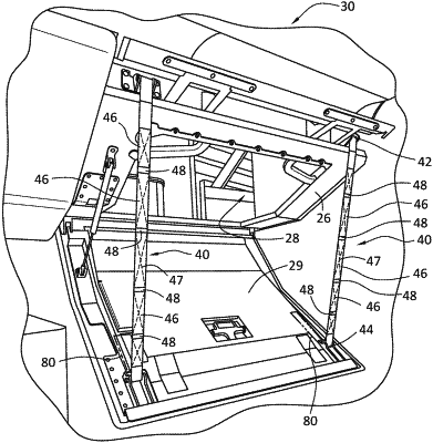
a crew egress pathway exit assembly, said crew egress pathway exit assembly comprising: an exit hatch support structure, said exit hatch support structure positioned at a crew egress pathway exit assembly, said crew egress pathway exit assembly in communication with a crew egress pathway; a movable exit hatch, said movable exit hatch in movable communication with the exit hatch support structure, a one-piece support strap in communication with the exit hatch support structure, said one-piece support strap further in communication with said movable exit hatch, said one-piece support strap comprising:
a support strap first end and a support strap second end, said support strap first end fixedly attached to the exit hatch support structure, said support strap second end fixedly attached to the movable exit hatch, said one-piece support strap comprising a plurality of support strap first sections, said plurality of support strap first sections comprising a first bending stiffness, at least two of the plurality of the support strap first sections adjoining an adjacent support strap second section, said support strap second section comprising a second bending stiffness, said second bending stiffness less than the first bending stiffness, said support strap second section interposed between two of the plurality of support strap first sections, said adjacent support strap second section configured to bend at the support strap second section as a flexible joint along a length of the one-piece support strap; wherein said movable exit hatch is in movable communication with the exit hatch support structure, said movable exit hatch configured to move through a range of motion from a stowed position to a deployed position with the movable exit hatch at least partially disengaged from the exit hatch support structure in the deployed position, with the movable exit hatch in substantial contact with the exit hatch support structure in the stowed position, and with the one-piece support strap in a stacked orientation in the stowed position;
wherein during moving the movable exit hatch from the deployed position to the stowed position the one-piece support strap is configured to form a folded one-piece support strap, said folded one-piece support strap configured to return into the stacked orientation and to occupy a predetermined folded one-piece support strap footprint in the stacked orientation;
wherein during moving the movable exit hatch from the stowed position to the deployed position the one-piece support strap is further configured to unfold at predetermined positions along the length of the one-piece support strap to form an unfolded one-piece support strap configured to unfold from the stacked orientation;
wherein the one-piece support strap comprises a plurality of flexible joints along a length of the one-piece support strap, said plurality of flexible joints configured to each rotate about an opposite axis of rotation relative to each prior and subsequent flexible joint, with the one-piece support strap configured to repeatedly fold upon itself into the stacked orientation; and
wherein the plurality of the support strap first sections each comprise a support strap first section diameter thickness, and said support strap second section comprises a support strap second section diameter thickness that differs from support strap first section diameter thickness.
|