| CPC B62D 7/222 (2013.01) [B60Q 5/003 (2013.01); B60R 21/203 (2013.01); B60R 21/2037 (2013.01); F16F 1/38 (2013.01); F16F 1/3842 (2013.01); F16F 3/0873 (2013.01); F16F 7/1028 (2013.01); F16F 7/104 (2013.01); F16F 7/108 (2013.01); F16F 15/08 (2013.01); B29C 45/14336 (2013.01); B29K 2021/003 (2013.01); B29L 2031/721 (2013.01); F16F 2222/08 (2013.01); F16F 2224/0208 (2013.01); F16F 2224/025 (2013.01); F16F 2226/04 (2013.01); F16F 2226/042 (2013.01); F16F 2228/04 (2013.01); F16F 2230/0005 (2013.01); F16F 2234/02 (2013.01)] | 10 Claims |

|
1. A method of making a frequency-tuned vibration damper assembly for dampening vibrations in a steering wheel, said method comprising:
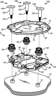
inserting a damper unit in an insertion direction into a mounting opening of a horn plate along an axis of the damper unit, said damper unit comprising an elastomeric damper element and a sleeve, said elastomeric damper element being molded on a radial outer side of the sleeve such that the sleeve and the elastomeric damper element together form a unitary structure, wherein the elastomeric damper element and the sleeve of the damper unit are inserted together as one unit into the mounting opening in the insertion direction until a final mounting position of the damper unit is reached, wherein the final mounting position of the damper unit comprises:
a plurality of radially outward extending snap-lock protrusions of the elastomeric damper element, formed at an insertion end of the damper unit, have been inserted in the insertion direction through the mounting opening to form a snap-lock of the damper unit in relation to the horn plate on a front side of the horn plate,
a radially outer elastomeric engagement surface of the elastomeric damper element, being axially spaced from the snap-lock protrusions and having a first radial dimension, has been inserted into the mounting opening and brought into radial engagement with a radially inner surface of the mounting opening of the horn plate, and
an elastomeric support part of the elastomeric damper element, having a second radial dimension larger than said first radial dimension, has been brought into axial contact with a rear side of the horn plate for defining the final mounting position;
inserting a guide shaft, in a direction opposite to the insertion direction, through a bore of the sleeve; and
connecting a distal end of the guide shaft to a base structure, which is fixed to the steering wheel and which is subjected to vibrations to be dampened, wherein the sleeve of the damper unit forms a slider being configured to slide along the guide shaft.
|