| CPC B62D 5/0484 (2013.01) [B62D 5/0424 (2013.01); B62D 5/046 (2013.01); B62D 5/0463 (2013.01); B62D 5/0496 (2013.01); H02K 7/003 (2013.01); H02P 21/0089 (2013.01); H02P 21/22 (2016.02); H02P 27/085 (2013.01); H02P 27/12 (2013.01); H02P 29/025 (2013.01); H02P 29/028 (2013.01); H02P 29/032 (2016.02); B62D 5/0481 (2013.01)] | 12 Claims |

|
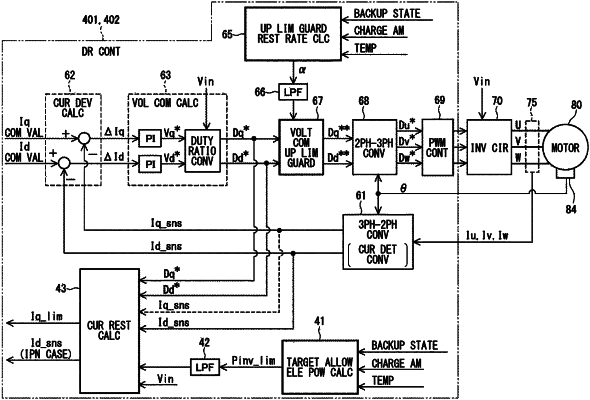
1. A motor control device for driving a motor by an electric power of a main power supply or a backup power supply in a system configured to be switchable between the main power supply as a direct current power supply having a large capacity and the backup power supply as a direct current power supply having a small capacity using a power supply switching determination unit, the motor control device comprising:
an inverter circuit that converts a direct current electric power from the main power supply or the backup power supply into an alternating current electric power, and supplies to the motor; and a drive control unit that outputs a drive signal, which is obtained by a feedback control of a current detection value with respect to a current command value, wherein:
the drive control unit includes:
a current detection value conversion unit that performs coordinate conversion of a detection value of a phase current flowing from the inverter circuit to the motor, and calculates a d-axis current detection value and a q-axis current detection value;
a voltage command value calculation unit that calculates a voltage command value to be applied to the inverter circuit or a d-axis voltage command value and a q-axis voltage command value as correlation values of the voltage command value so that the d-axis current detection value and the q-axis current detection value follow a d-axis current command value and a q-axis current command value, respectively; and
a voltage command upper limit guard unit that guards an upper limit of an absolute value of each of the d-axis voltage command value and the q-axis voltage command value by a voltage command upper limit guard value; and
when the power supply switching determination unit switches from the main power supply to the backup power supply, the drive control unit shifts from a normal control, executed when the main power supply is used, to a backup control that prevents the backup power supply from stopping by restricting an electric power consumption.
|