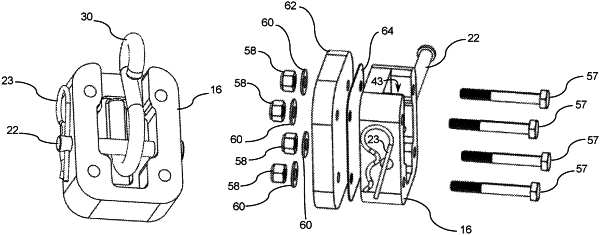
| CPC B60R 9/04 (2013.01) [B60P 7/0807 (2013.01); B60R 9/058 (2013.01)] | 12 Claims |

|
1. An anchor bracket assembly comprising:
a bracket body comprising:
a top surface;
a bottom surface opposite the top surface and displaced from the top surface along a vertical axis;
first and second side surfaces extending between the top and bottom surfaces and oriented parallel to the vertical axis and parallel to a longitudinal axis that is perpendicular to the vertical axis;
first and second end surfaces each extending between the top and bottom surfaces and between the first and second side surfaces, the first and second end surfaces oriented parallel to the vertical axis and perpendicular to the longitudinal axis;
a cavity having an opening in the top surface, and a cavity base surface oriented parallel to the top surface and displaced from the top surface along the vertical axis;
a strap slot formed through the top surface and the first end surface and extending along the longitudinal axis to the cavity;
a hook slot recessed along the vertical axis from the cavity base surface and extending along the longitudinal axis, the hook slot defined by a hook slot base surface oriented parallel to the cavity base surface, opposing hook slot end walls displaced from each other along the longitudinal axis and extending along the vertical axis from the hook slot base surface, and opposing hook slot side walls extending between the hook slot end walls along the longitudinal axis, displaced from each other along a horizontal axis that is perpendicular to the longitudinal and vertical axes, and extending from the hook slot base surface along the vertical axis;
at least two mounting holes each extending along the vertical axis from the top surface to the bottom surface;
a first pin bore extending through the first side surface to the cavity along the horizontal axis; and
a second pin bore extending through the second side surface to the cavity along the horizontal axis; and
a pin member extending through the first and second pin bores and the cavity.
|